Posts: 7,294
Threads: 268
Joined: Dec 2009
City: Roslyn Pa
Just as a side bar the model 95 is a very similar set with the same sort of FC set up as a bleeder for the power supply. It's using an 8.3K resistor there. I'd give that a go.
On the old harness I generally try not flex them much while servicing. If it is just few wires I'd use shrink tube over it an leave it alone.
When my pals were reading comic books
I was down in the basement in my dad's
workshop. Perusing his Sam's Photofoacts
Vol 1-50 admiring the old set and trying to
figure out what all those squiggly meant.
Circa 1966
Now I think I've got!
Terry
Posts: 16,220
Threads: 562
Joined: Oct 2011
City: Jackson
State, Province, Country: NJ
I miswrote -43 is a cap, not a resistor. If 45 is Ok then it should be fine.
All wirewounds are OK?
Are all plate voltages present across all tubes?
Heres what I don't get: high voltage you saw means low power draw. Just the output stage should provide e ough draw.
Ok, resistors 16 and 36.
People who do not drink, do not smoke, do not eat red meat will one day feel really stupid lying there and dying from nothing.
Posts: 35
Threads: 6
Joined: Sep 2016
City: Gas City,IN
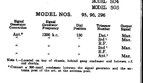
I replaced #41 with a 800 ohm 10W power resistor and the set works now and fixed all my pin voltage problems. I also rewired the whole chassis to fix all the brittle wiring. I'm kind of sad that I had to lose all that gorgeous cloth wiring but it is safer. My final question. Does anyone have the alignment instructions for this Philco Model 96?
Posts: 1,475
Threads: 69
Joined: Nov 2012
City: Kansas city, MO.
Posts: 16,220
Threads: 562
Joined: Oct 2011
City: Jackson
State, Province, Country: NJ
On the page 4 of the Rider's doc is the trimmer's alignment list.

People who do not drink, do not smoke, do not eat red meat will one day feel really stupid lying there and dying from nothing.


![[-] [-]](https://philcoradio.com/phorum/images/bootbb/collapse.png)


