Welcome Guest! Be sure you know and follow the Phorum Rules before posting. Thank you and Enjoy! (January 12) x

Thread Closed
Thread Rating:
  • 0 Vote(s) - 0 Average
  • 1
  • 2
  • 3
  • 4
  • 5

38-09 Electrolytic question
#1

https://philcoradio.com/library/download...l.%202.pdf

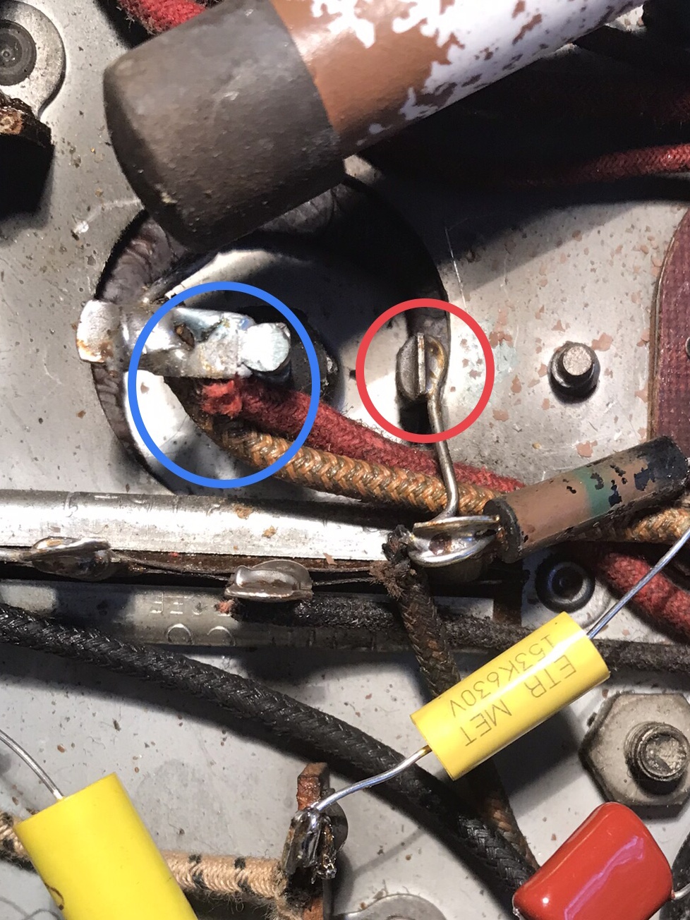
I’m working on a Philco 38-09 and I have a question regarding one of the electrolytic caps, part #45. The enclosed photo showing the blue circle is the 25 mfd cap with two wires attached to it. The two-tone yellow/green wire goes to the field coil and the red goes to Pin 6 of the 5Y4 tube where it is connected with a black wire that goes to the power transformer. I’m assuming that is my + connection for my replacement cap and the red circle is my - connection.

I’m still new to this hobby and I hoped someone could confirm whether I’m correct and enlighten me as to the purpose of why this cap is connected to the 5Y4 tube and not directly into the power transformer.     
#2

The one going to the rectifier tube's filament, field coil and transformer - PLUS
The other one is minus.

People who do not drink, do not smoke, do not eat red meat will one day feel really stupid lying there and dying from nothing.
#3

Red circle is the - side and blue the +. You may want change the 38-09 to 38-9 it's less confusing.

When my pals were reading comic books
I was down in the basement in my dad's
workshop. Perusing his Sam's Photofoacts
Vol 1-50 admiring the old set and trying to
figure out what all those squiggly meant.
Circa 1966
Now I think I've got!

Terry
#4

I can see a Candohm...

People who do not drink, do not smoke, do not eat red meat will one day feel really stupid lying there and dying from nothing.
#5

Thanks Morzh and Terry.
#6

Hi Hamilton, the answer to your question regarding 5Y4 pin 6 is pin 6 is an unused pin so is being used as a termination point. You will see this often especially for B+ or B-.
#7

Perfect thanks Rod. Appreciate the explanation.


Users browsing this thread: 2 Guest(s)
[-]
Recent Posts
The list of my radio & TV collection!
Hello Peter, Thank you for posting that !! Sincerely Richardradiorich — 09:40 AM
Eico 232 VTVM Schematic
It's a microwave antenna. ?;-p?. I substituted 1N4002s off the 6.3 vac winding for the 1.5 volt battery. Uniprobe is the...RodB — 05:50 PM
Eico 232 VTVM Schematic
Try BAMA for a schematic. Looks like a replacement power source for the D battery has been installed. The tube may be...Chas — 04:51 PM
Eico 232 VTVM Schematic
Is that a battery holder?morzh — 04:43 PM
Eico 232 VTVM Schematic
A friend gave me this Eico 232 VTVM and I'm having trouble locating the schematic for it. This one seems to be a later v...RodB — 04:17 PM
Var resistor id
Considering what it is in series with, I doubt there should be any power requirements. Of course, we should know wher...morzh — 03:23 PM
Var resistor id
Trim pot, about 1/2 watt part of focus divider. As stated 2k ohms. This appears to be a rusty chassis, resolder all ...Chas — 03:19 PM
Var resistor id
Its a Sylvania 400 oscilloscope. here is a clip of r-100. Would be nice to know the current required. Not listed in part...Martinj — 02:10 PM
The list of my radio & TV collection!
Thanks Richard. I hope you enjoy it. Here I have created an English section on the history of radio with videos in Engl...RadioSvit — 10:23 AM
The list of my radio & TV collection!
Hello RadioSvit, first all happy new year ! I will watch your new videos this week. Sincerely Richardradiorich — 09:19 AM

[-]
Who's Online
There are currently 9496 online users. [Complete List]
» 2 Member(s) | 9494 Guest(s)
AvatarAvatar

>