Welcome Guest! Be sure you know and follow the Phorum Rules before posting. Thank you and Enjoy! (January 12) x

Thread Closed
Thread Rating:
  • 0 Vote(s) - 0 Average
  • 1
  • 2
  • 3
  • 4
  • 5

Philco 45 chassis restoration
#1

Hello all,

I have finished my 45 cabinet and now it is time to restore the chassis.
I have my chassis and a chassis I got for a friend. The chassis are quite different. I think mine is all jerry-rigged and I dont know how to change it back to original. I have included pictures of the differences so if anyone can explain and tell me how to return it to original I would be grateful.

First picture is of my chassis with 2 transformers. The second picture is of the other chassis but has only one transformer.
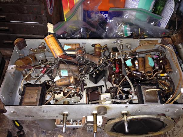
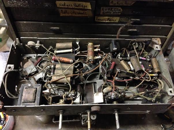


The next picture is of my chassis where there is a braided ground wire across the chassis and the second chassis does not have it.
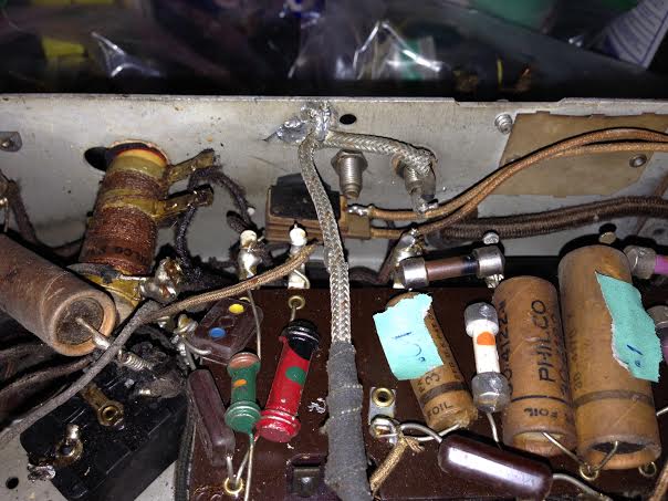
   

The next pic is of my chassis with 2 caps added in where the other chassis has neither. I think these were to bypass the bakelite block?
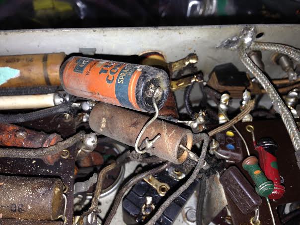
   

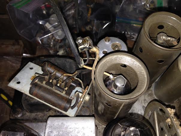
The next photo is of something odd. there is a wire coming off the transformer on top of the chassis that should be attached to the tube but it is attached to a broken tube top with a wire going to a plug with a switch and 2 .047 caps. I have no idea what this is...
   

Times I have been electrocuted in 2021
As of 1/01/2021
AC: 4 DC: 1
Last year: 6
#2

The next pic is of a missing tube socket that is supposed to be coming out the back of the chassis where the other chassis has it. In the pictures there is also a missing bakelite block in mine.


Lastly there is a switch on the back of my chassis and not one in the other chassis. what is this switch for? and was it original or added??

Any help is appreciated and i know it is alot to ask

Kirk

Times I have been electrocuted in 2021
As of 1/01/2021
AC: 4 DC: 1
Last year: 6
#3

Without looking at the schematic, I would think the extra trans is probably for the speaker, is your freinds a console? And the strange switch is probably a phono input.
#4

Your chassis is for a table set and the other chassis looks to be for a console. The switch with the two caps is a phono input, it can be removed if you have no intensions of using it.

Gregb
#5

Ok I did not even know there were 2 different ones.
So I will remove the switch and I guess I'll have to try going by the schematics. The only other question is that orange and black cap. The mfd is scratched off. I cant find it on the schematic

Kirk

Times I have been electrocuted in 2021
As of 1/01/2021
AC: 4 DC: 1
Last year: 6
#6

I cant really see what its connected to but my guess would be the orange and black cap and the one right next to it are to replace the dual .09 uf caps the are in the bakelite block direct below them.

Gregb


Users browsing this thread: 1 Guest(s)
[-]
Recent Posts
6TPZ and 5TPO Radio Help
Since these radios operated in harsh environments (temp changes and vibration) you could touch a soldering iron to all t...GarySP — 03:18 PM
6TPZ and 5TPO Radio Help
Thank you Gary. Hi Morzh. These radios are 6 transistor radios. Sadly no tubes. Thanks though.R3Sons — 02:19 PM
Heathkit Sweep Generator TS-4
Ron Instead of Quick reply, go to New Reply, then go to the title of the very first post, and change the title text the...morzh — 02:00 PM
6TPZ and 5TPO Radio Help
I am not a specialist in car radios. I suspect they might use vibrators to convert 12V to acceptable tube voltages, so ...morzh — 01:58 PM
6TPZ and 5TPO Radio Help
Welcome to the Phorum, R3Sons! I have very limited experience with car radios other than installing custom radios back ...GarySP — 01:08 PM
462ron
OK, I need to rename this thread to say..Eico 368 TV/FM Sweep Generator instead of the current title..Heathkit Sweep Gen...462ron — 12:49 PM
6TPZ and 5TPO Radio Help
Hello, I have a Philco (Ford) 6TPZ and a 5TPO radio.  I replaced the electrolytic capacitors in both.  I have the SAMS m...R3Sons — 12:29 PM
The list of my radio & TV collection!
Hello Peter, Thank you for posting that !! Sincerely Richardradiorich — 09:40 AM
Eico 232 VTVM Schematic
It's a microwave antenna. ?;-p?. I substituted 1N4002s off the 6.3 vac winding for the 1.5 volt battery. Uniprobe is the...RodB — 05:50 PM
Eico 232 VTVM Schematic
Try BAMA for a schematic. Looks like a replacement power source for the D battery has been installed. The tube may be...Chas — 04:51 PM

[-]
Who's Online
There are currently 8900 online users. [Complete List]
» 1 Member(s) | 8899 Guest(s)
Avatar

>