Welcome Guest! Be sure you know and follow the Phorum Rules before posting. Thank you and Enjoy! (January 12) x

Thread Closed
Thread Rating:
  • 0 Vote(s) - 0 Average
  • 1
  • 2
  • 3
  • 4
  • 5

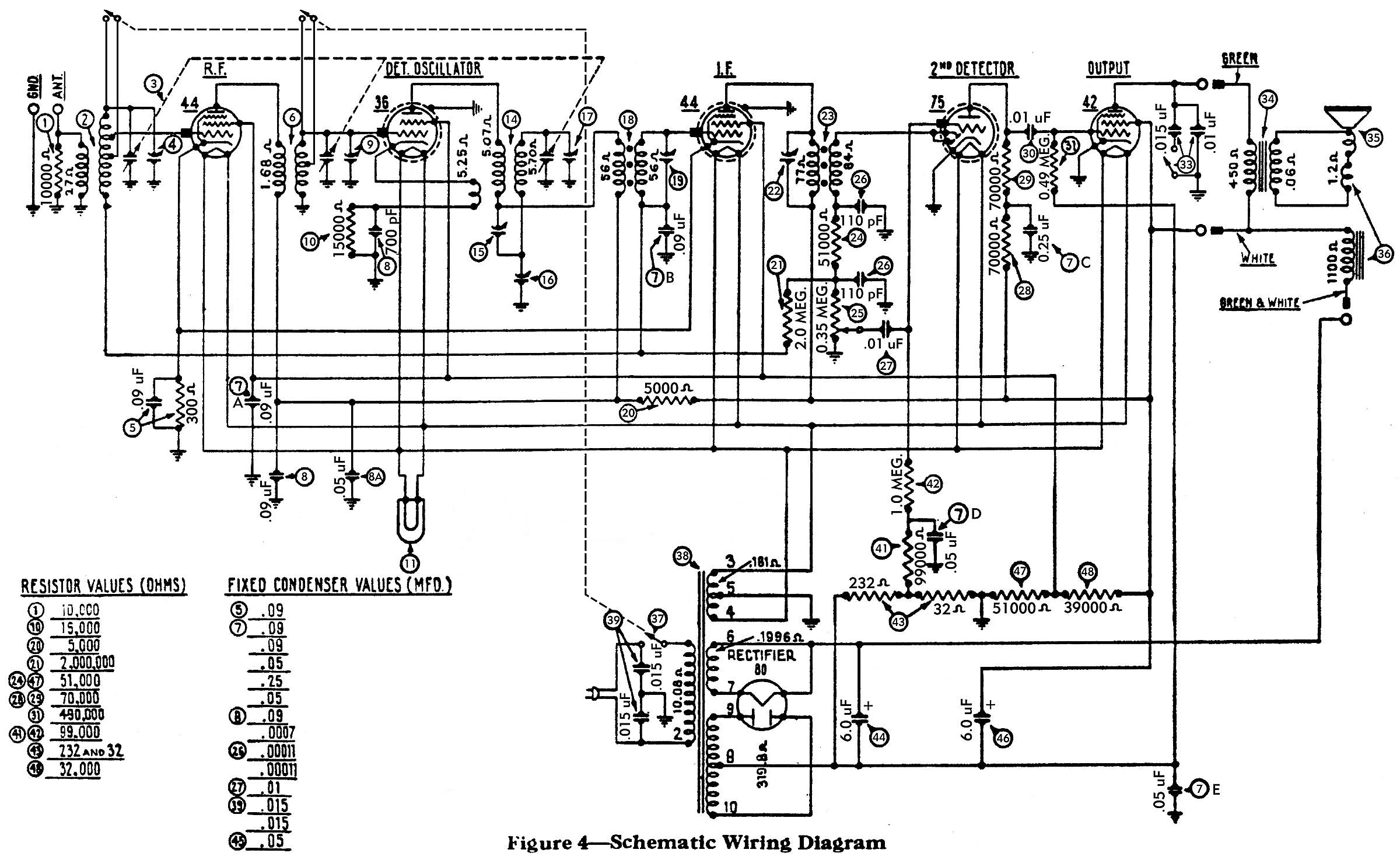
cap questions on model 89 (version 6 schematic)
#1

I really could use another pair of eyes and some good advice here from those more experienced than I. I'm trying to replace the caps in the #7 Filter condenser bank. There are 5 caps in that "bank", each are number 7 on the attached schematic. I'm trying to find where the .09 mfd's go? It almost looks like two of them go to the #44 RF tube on the front corner of the chassis. The other end goes to ground, of course.

The other question I have concerns the #5 bakelite block. There's a .09 mfd cap in the block along with a 300 ohm resistor. Should there be a wire going from one terminal of the block to the #41 (99,000 ohm) resistor? There are two wires coming from the variable capacitor going to the ground terminal on the bakelite block. Is that correct? Also does one wire from this block go to the antenna coil?

I'm sure to most of you, these will all appear to be obvious. I just want to verify that what I'm doing is correct. You can never be too sure! Icon_smile Thanks in advance.


Greg V.
West Bend, WI
Member WARCI.org
#2

It looks like 1 .09 goes to the grid of both 44's and the 36 the other .09 goes to coil #18 and the ant coil
#3

The #5 block is in series to ground from pin 4 of both 44's. They are probably just using the ground conection on the block because it was the closest/convenient ground.
#4

The cap going to resistor 41 should be a .05
#5

Thanks, tab. My chassis was a mess... someone, sometime long, long ago added and replaced a bunch of stuff and so much of what was reconnected was soldered onto the wrong lugs. I'm going through the schematic with a highlighter pen trying to trace out each and every wire / connection / component. A daunting process. The .05 cap between the 41 & 42 resistors was an easy one to find. But on my chassis, there was a wire going from the #5 block to the 41 resistor. I'm thinking it doesn't belong there.

Greg V.
West Bend, WI
Member WARCI.org


Users browsing this thread: 1 Guest(s)
[-]
Recent Posts
Eico 368 TV/FM Sweep Generator
Ron, for the future: In order to change the name of teh topic, 1. Go to the very first post. 2. Hit "Edit...morzh — 04:29 PM
6TPZ and 5TPO Radio Help
Transistors are easy. No converters. If you have input voltage, then just put some signal through. Or touch your fin...morzh — 04:25 PM
462ron
Hi Mike, I believe I tried different ways to change the header for my post but no luck. Anyway thanks for changing it fo...462ron — 04:02 PM
6TPZ and 5TPO Radio Help
Since these radios operated in harsh environments (temp changes and vibration) you could touch a soldering iron to all t...GarySP — 03:18 PM
6TPZ and 5TPO Radio Help
Thank you Gary. Hi Morzh. These radios are 6 transistor radios. Sadly no tubes. Thanks though.R3Sons — 02:19 PM
Heathkit Sweep Generator TS-4
Ron Instead of Quick reply, go to New Reply, then go to the title of the very first post, and change the title text the...morzh — 02:00 PM
6TPZ and 5TPO Radio Help
I am not a specialist in car radios. I suspect they might use vibrators to convert 12V to acceptable tube voltages, so ...morzh — 01:58 PM
6TPZ and 5TPO Radio Help
Welcome to the Phorum, R3Sons! I have very limited experience with car radios other than installing custom radios back ...GarySP — 01:08 PM
462ron
OK, I need to rename this thread to say..Eico 368 TV/FM Sweep Generator instead of the current title..Heathkit Sweep Gen...462ron — 12:49 PM
6TPZ and 5TPO Radio Help
Hello, I have a Philco (Ford) 6TPZ and a 5TPO radio.  I replaced the electrolytic capacitors in both.  I have the SAMS m...R3Sons — 12:29 PM

[-]
Who's Online
There are currently no members online.

>