02-07-2015, 09:56 PM
This is the next project at the Rossi house. This was given to me by my sister and brother-in-law, who got it from someone they know in Tennessee. The S-41G was a starter radio, and is fairly common. There is a peculiarity on the front panel:
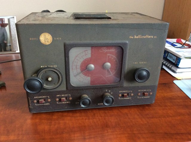
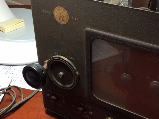
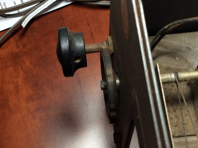
There is an added knob on the front panel. A very ingenious 'gear' reduction method was added so that the tuning knob turns very incrementally and acts as a fine tuner. I've never seen this before. Here is a pic of the internal portion of the shaft assembly and a close-up of the front:
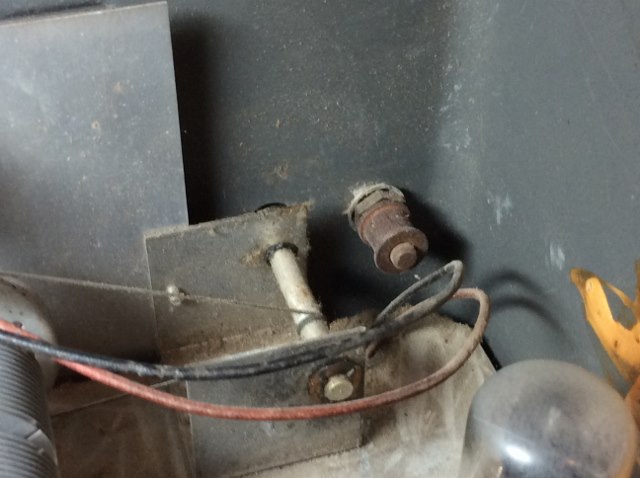
The radio was filthy on the inside, and there is more cleaning to do. Surprisingly, except for the metal electrolytic, it all looks original.
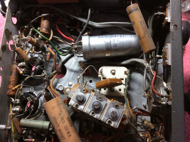
In turning the bandspread this dial cord snapped. I have ordered some cord and will restring both that and the main tuning. Nearly every resistor looks crisp and fresh, the cap's with a few exceptions look new. Every last cap will be replaced, and seeing that it is an AA6, I will isolate the ground by using a polarized plug so that the ground is always connected to the chassis B-, and putting the switch back in the hot line so when you shut the radio off there's really no power in the circuit. I found that on the S-38 Guy website and quote directly from this very wise person. As I go forward I'll do further posts.
There is an added knob on the front panel. A very ingenious 'gear' reduction method was added so that the tuning knob turns very incrementally and acts as a fine tuner. I've never seen this before. Here is a pic of the internal portion of the shaft assembly and a close-up of the front:
The radio was filthy on the inside, and there is more cleaning to do. Surprisingly, except for the metal electrolytic, it all looks original.
In turning the bandspread this dial cord snapped. I have ordered some cord and will restring both that and the main tuning. Nearly every resistor looks crisp and fresh, the cap's with a few exceptions look new. Every last cap will be replaced, and seeing that it is an AA6, I will isolate the ground by using a polarized plug so that the ground is always connected to the chassis B-, and putting the switch back in the hot line so when you shut the radio off there's really no power in the circuit. I found that on the S-38 Guy website and quote directly from this very wise person. As I go forward I'll do further posts.
Joe
Matthew 16:26 "For what does it profit a man if he gain the whole world, yet lose his own soul?"


![[-] [-]](https://philcoradio.com/phorum/images/bootbb/collapse.png)


