Model 90 Output Transformer
Posts: 26
Threads: 4
Joined: Feb 2016
City: Nelson
State, Province, Country: BC
I'm working on restoring a Philco Model 90 (2 45's for output, Min-max switch, March 1931). It was recapped but not working when I received it. I was not impressed with the quality of the previous work...
Lack of plate voltage to the first 45 (the second 45 is getting 243V at the plate) led me to look at the speaker output transformer wiring. I'm convinced that the wiring is not correct and also that the output transformer is bad. The transformer is a Jefferson Electric 2766J but I have no info on its wiring layout. Checking continuity between leads shows pretty much everything open. There are 2 end connection lugs on each side with center wires also on each side. One side has a black center wire, the other is red (or orange?). Does anyone have any info on which is primary/secondary and start/finish/center tap?
I'm looking at the Hammond 125C as a replacement for this transformer. Other threads lead me to believe it will work in this context.
I'd appreciate any advice!
Posts: 5,129
Threads: 271
Joined: Nov 2012
City: Wilsonville
State, Province, Country: OR
Welcome to the Phorum!

I can't help you with that question but someone will chime in soon.
Posts: 16,272
Threads: 566
Joined: Oct 2011
City: Jackson
State, Province, Country: NJ
125C is pretty universal and does work for most pushpull baby grands. I used it for 20 and 20 output transformer is very much like 90 pushpull.
2766 has 1:100 ratio which makes impedance increase 10,000 times.
125B or C (either one I think is fine; I used C) if connected to secondary 3-4 lugs gives very close ratio to that (1.5 : 16,500 is approx. equal to 10,000)
People who do not drink, do not smoke, do not eat red meat will one day feel really stupid lying there and dying from nothing.
Posts: 7,294
Threads: 268
Joined: Dec 2009
City: Roslyn Pa
Standard color code for audio output transformer primary is Blue lead is the plate(top), Red lead is B+(ct), Brown is the other Plate lead for P/P output (bottom). Secondary is Green or copper wire.
Terry
Posts: 26
Threads: 4
Joined: Feb 2016
City: Nelson
State, Province, Country: BC
Thanks for the replies! I'm very happy to have found this forum and the great knowledge here.
The wires are so faded that color identification is difficult in this case. I think the best thing for me is to replace the transformer with a known entity since it appears to be open. On to the next mystery in this endeavor!
Posts: 4,816
Threads: 54
Joined: Sep 2008
City: Sandwick, BC, CA
(03-02-2016, 03:52 AM)rrova Wrote: I'm working on restoring a Philco Model 90 (2 45's for output, Min-max switch, March 1931). It was recapped but not working when I received it. I was not impressed with the quality of the previous work...
Lack of plate voltage to the first 45 (the second 45 is getting 243V at the plate) led me to look at the speaker output transformer wiring. I'm convinced that the wiring is not correct and also that the output transformer is bad. The transformer is a Jefferson Electric 2766J but I have no info on its wiring layout. Checking continuity between leads shows pretty much everything open. There are 2 end connection lugs on each side with center wires also on each side. One side has a black center wire, the other is red (or orange?). Does anyone have any info on which is primary/secondary and start/finish/center tap?
I'm looking at the Hammond 125C as a replacement for this transformer. Other threads lead me to believe it will work in this context.
I'd appreciate any advice!
The existing transformer could also be miswired, the B+ should always go to the center tap of the primary, so it's worth disconnecting and rechecking. As for replacements pretty much any push pull output transformer should work, except if it's for 41/6K6 tubes, the primary impedances are pretty close between 45s, 47s, 42s/6F6s, 6V6s, 6L6s, and 6BQ5s, it isn't that critical.
Regards
Arran
Posts: 26
Threads: 4
Joined: Feb 2016
City: Nelson
State, Province, Country: BC
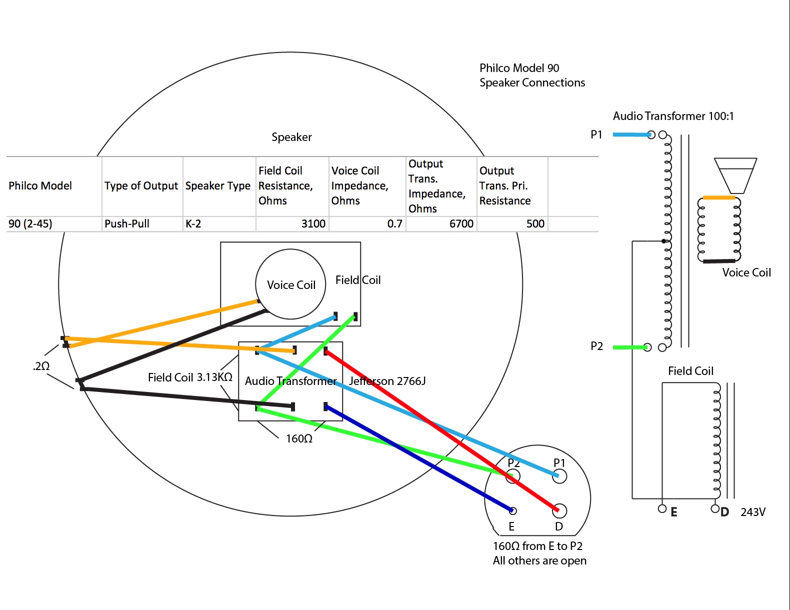
Thanks Arran for the input. I will remove the transformer later today and test it. Here is what the wiring looks like now:

But this doesn't make sense to me...
(This post was last modified: 03-04-2016, 06:09 AM by rrova.)
Posts: 16,272
Threads: 566
Joined: Oct 2011
City: Jackson
State, Province, Country: NJ
So, P1 to P2 (field) is open? First it is wired wrong.
P1 and P2 pins should be the field coil pins.
http://www.philcoradio.com/tech/speaker.htm
People who do not drink, do not smoke, do not eat red meat will one day feel really stupid lying there and dying from nothing.
Posts: 26
Threads: 4
Joined: Feb 2016
City: Nelson
State, Province, Country: BC
Hmmm. I think the drawing you refer to is for single-ended output (one pin is not used). For push-pull output all pins are used.
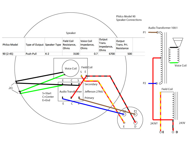
Based on the schematic (as shown at the right side of this illustration) I was expecting the wiring to be something more like this, perhaps I'm wrong:

Posts: 16,272
Threads: 566
Joined: Oct 2011
City: Jackson
State, Province, Country: NJ
It doesn't matter, with cut side down the top two pins are ALWAYS the field coil.
In your case:
If you look at pins from the front,
P1-P2 are field coil.
P2 is also the center tap of the xfmr primary.
E and D are the Pushpull ends of the primary.
Or as Arran suggested: it is grossly miswired.
PS. It is also possible that whoever fixed the radio the first time also miswired the chassis socket and then wired the plug to fit.
You have to see what chassis is like.
PPS. I'd still made the wiring standard lest you one day burn a perfectly good speaker plugging it in your chassis.
People who do not drink, do not smoke, do not eat red meat will one day feel really stupid lying there and dying from nothing.
Posts: 26
Threads: 4
Joined: Feb 2016
City: Nelson
State, Province, Country: BC
Thank you for the clarification. In the first diagram, I am showing how it is currently wired, I have traced it in the chassis and through the speaker connection. If convention is that the top two are the field coil, then I will rewire the chassis as well.
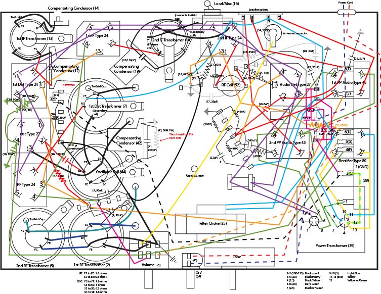
Here's how it currently looks (note: the interstage audio transformer has been replaced by a phase inverter circuit--at least that's what it appears to be):

Posts: 16,272
Threads: 566
Joined: Oct 2011
City: Jackson
State, Province, Country: NJ
To be honest....?how do I know which pins are top and which are bottom?
You have the actual chassis, it is easier for you to look at it.
If I were to think the two inner pins are at the bottom (well the chassis is upside down so right now they are at the top), but I mean one fat and one slim pin, they have to be pushpull xfmr ends.
The two outer pins (two fat ones, again I am making a supposition) have to be the field coil. One of them also receives the centertap. (If you look at the plug, the top left fat one connects to both field and center tap).
It seems to me that if my presumtions were correct, your chassis is miswired same way your speaker is.
People who do not drink, do not smoke, do not eat red meat will one day feel really stupid lying there and dying from nothing.
Posts: 26
Threads: 4
Joined: Feb 2016
City: Nelson
State, Province, Country: BC
Yes, the two inner pins are at the bottom (they are labeled with T's & B's in the diagram for Top & Bottom). I agree that chassis and transformer are not wired correctly. I was unaware of the speaker pin wiring convention that you clarified for me, and I appreciate that. Thank you!
I made this rat's nest diagram to help me in identifying the connections as I trace through the circuits (and to make sure I know which tube pin is which). I'm using a signal generator, a 'scope and a signal tracer along with voltage measurements to identify problem areas. With the diagram and the original schematic I can usually keep track of where I am in the circuit analysis. Also, making the diagram helped me to find incorrect values for some components, missing components, and miswired connections.
Posts: 16,272
Threads: 566
Joined: Oct 2011
City: Jackson
State, Province, Country: NJ
Does it look from solder joints (like on the speaker socket, or elsewhere) that the radio had been repaired before?
What I think might've happened, someone miswired the speaker plug, and then, since it is a laborious process, preferred to rewire the socket accordingly as it is easy.
People who do not drink, do not smoke, do not eat red meat will one day feel really stupid lying there and dying from nothing.
Posts: 26
Threads: 4
Joined: Feb 2016
City: Nelson
State, Province, Country: BC
Yes, I can see that it's been worked on before. The soldering was not well done. I've re-soldered a number of connections that were sloppy or loose. Also, lots of very thin wiring that I've started replacing with vintage cord.
Users browsing this thread: 12 Guest(s)
|
|
Recent Posts
|
|
RCA T62 is playing.....
|
| Beautiful set.morzh — 09:07 PM |
|
An attempt to remove the Field Coil from a G speaker
|
| Well....here it is.
The green stuff. Unfortunately, probably penetrates deep.
I opened the top layer and saw that:
...morzh — 08:58 PM |
|
Philco 91 Restore Code ??
|
| :clap: :clap: :clap: :clap:
Really nice workmanship!!! Top of the chassis looks great.
Sorry about the long winded e...MrFixr55 — 08:09 PM |
|
Philco 40-120C Restoration
|
| Thank you for your reply. I will check voltages on the other tubes, look at resistor 23 and cap 25, etc. If all else fai...bluecap — 07:58 PM |
|
RCA T62 is playing.....
|
| Nice looking set great save. DavidDavid — 07:48 PM |
|
Philco 89 indicator light.
|
| Hello Jim, I have done several 89s. The trick is to move the drum in or out on it's shaft. You will need to loosen a set...dconant — 07:36 PM |
|
An attempt to remove the Field Coil from a G speaker
|
| MrFixr
Yes, it is my plan to go with 45rpm spider if I go that far.
No, the pole was not left-handed as I unscrewed ...morzh — 07:14 PM |
|
Philco 40-120C Restoration
|
| Change the tube. Check the tube's bias network.
Are any other tubes experience the drop or just this?`
Is resistor 23 OK...morzh — 07:09 PM |
|
Philco 89 indicator light.
|
| I forgot how the pointer is formed: could you show the way it is formed and how you tried to change it?morzh — 07:01 PM |
|
An attempt to remove the Field Coil from a G speaker
|
| Was that pole piece left handed ?
Since the metal "spider" is toast, wonder if you can either get the "4...MrFixr55 — 06:54 PM |
|
Who's Online
|
There are currently 7435 online users. [Complete List]
» 3 Member(s) | 7432 Guest(s)
|
|
|

|
 
|


![[-] [-]](https://philcoradio.com/phorum/images/bootbb/collapse.png)


