Posts: 40
Threads: 9
Joined: Jul 2021
City: Franklin
State, Province, Country: Wisconsin
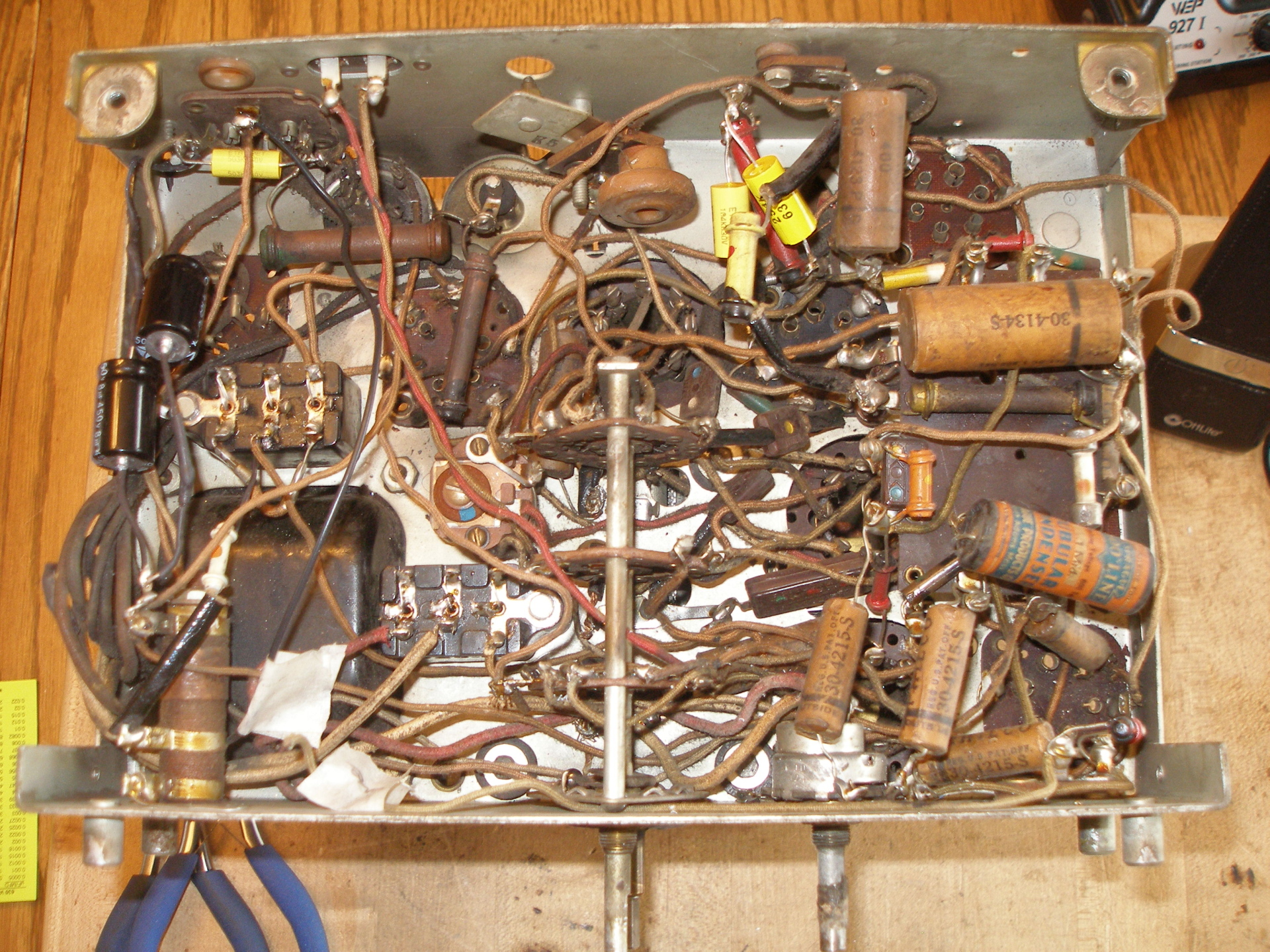
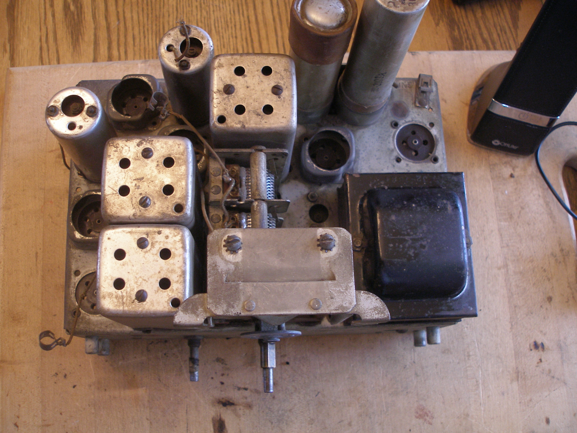
I have a Philco radio cabinet style is like the 630X or 640X in the Philco Gallery. Schematics are very similar with notable exceptions. First of all, my radio has only two Bakelite Condenser blocks. Schematics have 3. The wire wound resister #70 on the schematic has a 10uf cap in parallel with it. This radio does not have a cap in parallel with it. Without listing them all there are several other differences. There were no stickers on the cabinet and the only one I found in the cabinet was illegible. Except for tow, all the caps have Philco part numbers on them. Two are Sprague - looks like old ones. This radio does not seem to have been worked on in decades, one tube was a replacement tube. The chassis has a number stamped on the back D16098 and a number printed on the front 927 47 O.K.


Posts: 13,776
Threads: 580
Joined: Sep 2005
City: Ferdinand
State, Province, Country: Indiana
Hi,
Try this schematic.
https://philcoradio.com/library/download...20219B.pdf
It is for the late production version of model 630.
Incidentally, what you have is a 630 since it has six tubes. The 640 has seven tubes and four bands, and a larger chassis.
The late production 630 sets have small holes in the RF cans like yours, with screw adjustments inside. Early production 630 sets have large holes in the RF cans for 1/4 inch nut adjustments.
And it isn't a 635 since it has the large terminal board under the chassis, under the 75 tube. 635 sets don't have that.
Regarding the 10 uF cap (67) in parallel with the B-C resistor (70). This was originally part of a three section electrolytic can. Whoever replaced electrolytics in your set may very well have left out the 10 uF, 50 volt electrolytic, which would explain why you don't see one. Trace out the wiring against the schematic in the link above; you may find that the original 10 uF section is still in the circuit.
--
Ron Ramirez
Ferdinand IN
Posts: 40
Threads: 9
Joined: Jul 2021
City: Franklin
State, Province, Country: Wisconsin
My model does not have a phono jack / switch.
Posts: 13,776
Threads: 580
Joined: Sep 2005
City: Ferdinand
State, Province, Country: Indiana
Most of them did not. Ignore the radio-phono switch and phono pickup in the link I posted previously, it was included in the 630PF radio-phono only.
--
Ron Ramirez
Ferdinand IN


![[-] [-]](https://philcoradio.com/phorum/images/bootbb/collapse.png)


