116X bakelite block question
Posts: 120
Threads: 10
Joined: Jul 2011
City: Glendale, CA
Hi,
Hey All,
I've got a bakelite block capacitor question for a Philco 116X.
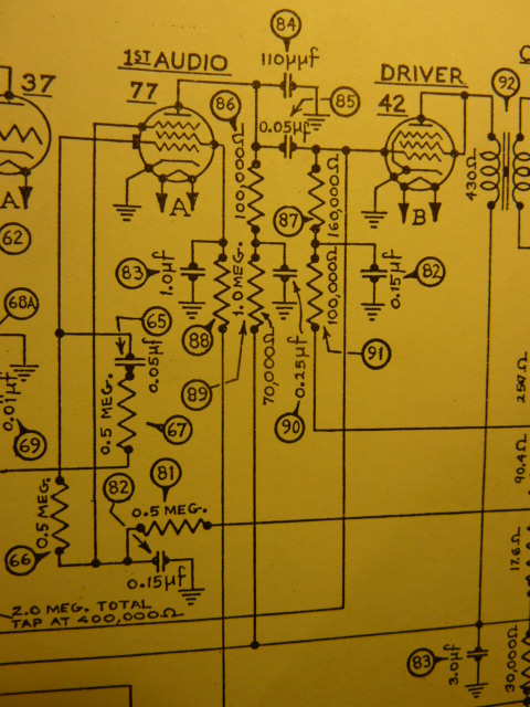
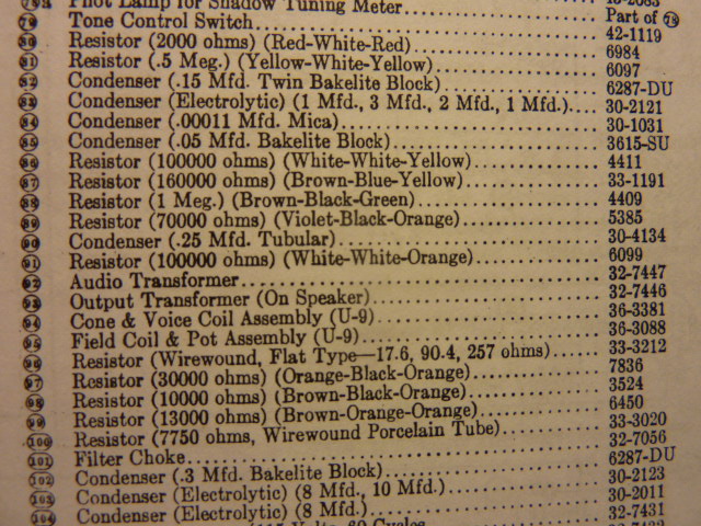
I'm only doing preliminary research right now, but I noticed that item # 82 and item #102, both bakelite blocks, have the same part number (6287-DU) but have different values in the part description.
Item # 82 (6287-DU) is described as .15 MFD, twin bakelite block and item # 102 (6287-DU) is described as .3 MFD bakelite block.
Has anyone any advice on how to handle this? I know that .15 + .15 = .3 and that might be related to this. What value capacitor(s) should I use and how am I supposed to connect this?
I'm confused as to what to do.
Thanks, Tom
Posts: 16,230
Threads: 563
Joined: Oct 2011
City: Jackson
State, Province, Country: NJ
Tom
If you have a link to the schematic (especially a nicer one than the one in the Rider), considering one has to look for an unknown version of 116X, point to it.
The numbers there are not legible.
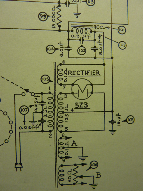
My guess is the 102 is the one across the filter choke.
I think what it could be is that in the 102 the parallel two caps, whereas in 82 they are used separately. Hence 0.15uF and 0.3uF.
It's a guess.
Posts: 120
Threads: 10
Joined: Jul 2011
City: Glendale, CA
Hey Morzh,
Thank you for the quick reply.
First of all, I believe you're right about # 102. One lead appears to connect to the filter choke.
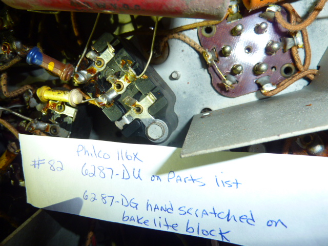
Just to complicate things, I looked underneath the chassis and found even more confusion. Someone's been busy in there. Bakelite part # 82 has been replaced. If you recall, the parts list shows # 82 and # 102 have the same part number, 6287-DU. "Someone" took a bakelite block, number 4989-DG, scratched that number out and scratched 6287-DG onto the side. The big problem is that the "G" in this part number means that the mounting screw grounds the bakelite block to the chassis. One of the block's capacitor wires is attached to this bolt's metal tab and is grounded to the chassis. The original part number, 6287-DU is an ungrounded block, which means the mounting screw is not grounded. The "U" in the part number means it's UNgrounded.
The only thing I can guess is that the parts list number is a misprint, or the replaced bakelite block is incorrect and the capacitor is miswired.
I've taken some pictures of this but I'm going to have to do some research on how to post them.
I know this may be somewhat confusing and I'll try and post some pictures.
Thanks for your help.
Tom
Posts: 16,230
Threads: 563
Joined: Oct 2011
City: Jackson
State, Province, Country: NJ
Tom
All that matter is whether ultimately the parts conform to the schematic or not.
In my 70 they changed some blocks places but ultimately the schematic holds, as two of the same type caps go in proper places.
Posts: 120
Threads: 10
Joined: Jul 2011
City: Glendale, CA
Morzh,
Here are some pictures. Maybe.


Tom
Posts: 120
Threads: 10
Joined: Jul 2011
City: Glendale, CA
Morzh,
Here are some pictures. Maybe.
[attachment=3757]
[attachment=3758]
[attachment=3759]
[attachment=3760]
The parts list picture shows the two bakelite blocks with the same part numbers, even though they're different underneath the chassis. # 82 is fifth from the top and # 102 is forth from the bottom.
I hope this helps. I can't believe I was able to post my first pictures!
Tom
Posts: 120
Threads: 10
Joined: Jul 2011
City: Glendale, CA
Well, the pictures are there, so that's a step in the right direction, but it appears I posted twice, partially. Sorry. I'll figure it out....eventually.
Tom
Posts: 5,126
Threads: 271
Joined: Nov 2012
City: Wilsonville
State, Province, Country: OR
Tom, in case you haven't seen this Philco Service Bulletin #289, its very helpful in understanding the bakelite blocks. The "D" means the two caps are the same value and the "G" means the first lug of the block is grounded to the chassis. In your photo of cap #82, lug 1 appears to be grounded thus they scratched in the DG. This is consistent with the two 0.15uF caps labeled "82" in the schematic since both are grounded on one end.
I don't know why they would have initially marked the block DU, perhaps a manufacturing error.
Posts: 16,230
Threads: 563
Joined: Oct 2011
City: Jackson
State, Province, Country: NJ
As I suspected 0.3uF is I think paralleled two of 0.15uF.
Ground lug is needed in 82 (should be DG) and not needed in 102 (should be DU).
Your pics in post #6 did not show up.
Posts: 120
Threads: 10
Joined: Jul 2011
City: Glendale, CA
Bob and Morzh,
Thanks so much for your help.
So, what you're saying is that the bakelite blocks # 82 and 102 are correctly wired in my radio, and # 82 on my parts list really should be chassis grounded and called a DG. The DU designation on my parts list, calling it ungrounded, is incorrect.
Morzh - The pictures on post 6 are really the pictures from post 5. I went back to edit and and add some information and made things even more confusing. Sorry.
Bob - I have seen Philco service bulletin # 289 and it was very helpful. The thing that really confused me was the parts list calling # 82 a DU, when in fact, it's a DG. To further complicate matters, that actual block had been replaced and 6287-DG was scratched on the side. The grounded/ungrounded letter didn't match according to the parts list, causing much confusion on my part.
Like I say, I'm still learning and I have a long way to go. I'm currently following along on You Tube with Joernone doing a 37-2670 restoration. I have a 37-670, which is almost identical, so I'm able to follow along and duplicate what he's doing. I'm learning a lot.
Thanks again for all your help.
Tom
Posts: 5,126
Threads: 271
Joined: Nov 2012
City: Wilsonville
State, Province, Country: OR
Yes, looks to me like they are wired per the schematic. The parts list seems to be in error for the #82 listing though I didn't see any correction in the "changes" service bulletins posted by Ron.
Posts: 120
Threads: 10
Joined: Jul 2011
City: Glendale, CA
Bob,
I've got the excellent schematic and service notes from Chuck Schwark, but there's no mention of a typo on the parts list for # 82.
Tom
Posts: 5,126
Threads: 271
Joined: Nov 2012
City: Wilsonville
State, Province, Country: OR
Well here's what I have to say about that....
[Image: https://dl.dropboxusercontent.com/u/5462...estion.jpg]

Users browsing this thread: 1 Guest(s)
|
|
Recent Posts
|
|
Model 27-84 BUZZ?Humm?
|
| Hello Bruce,
First all do mean a 37-84b ?
Did you take any before and after pictures ?
is it a buzz like when you touch...radiorich — 01:59 AM |
|
B&K 1077B no video - problem solved
|
| Hello Tim,
Yes, I even check all of my replacement parts when I install them and I too had a capacitor go bad not long a...radiorich — 01:54 AM |
|
B&K 1077B no video
|
| I got back into it tonight. Problem found and resolved! Sometimes it helps to take a break and think things over. It was...TV MAN — 12:40 AM |
|
6TPZ and 5TPO Radio Help
|
| Thank you. I have to take a break from it for about a week. I'll have to do some thinking. I was toying with the idea ...R3Sons — 12:21 AM |
|
Model 27-84 BUZZ?Humm?
|
| Drowning in a overloud buzz/Humm. Have already changed filter caps,bakelite blocks( caps),out of speck resistors,checked...Bruce — 12:17 AM |
|
Philco 630csx power cord
|
| Hello Mike
Here is the Link to the company the place is called Grand Brass lamp parts .
I buy all my Lamp parts plus ...radiorich — 12:00 AM |
|
Philco 40-120C Filament Wiring
|
| Is the tube in your radio actually 35Z3 or 35Y4, or something else?morzh — 10:55 PM |
|
Philco 630csx power cord
|
| Second Rich's opinion.
Run a separate antenna wire. Use a separate plug.
Rich
Where did you get this wire? Se...morzh — 10:51 PM |
|
6TPZ and 5TPO Radio Help
|
| On K2, pins 1&2 are shorted. On K4, Pins 1&3 are shorted. Others are OK. - your 0.047 caps are fried in both
Th...morzh — 10:40 PM |
|
Philco 630csx power cord
|
| Hello Tynwald ,
I would not use that plug and what I would do is us Some of this cloth covered wire !
you can also buy...radiorich — 10:28 PM |
|
Who's Online
|
There are currently 2534 online users. [Complete List]
» 1 Member(s) | 2533 Guest(s)
|
|
|

|
 
|


![[-] [-]](https://philcoradio.com/phorum/images/bootbb/collapse.png)


