Welcome Guest! Be sure you know and follow the Phorum Rules before posting. Thank you and Enjoy! (January 12) x

Thread Closed
Thread Rating:
  • 0 Vote(s) - 0 Average
  • 1
  • 2
  • 3
  • 4
  • 5

Zenith L403 Radio
#1

Hello Everyone!

Help is needed.  I am working on a Zenith L403 tabletop.  I have run into the following 10 Meg resistor which is not on the schematic or the parts list. 
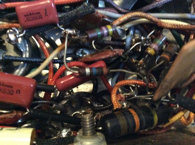
   

I have also included the schematic, showing where it is currently soldered in.
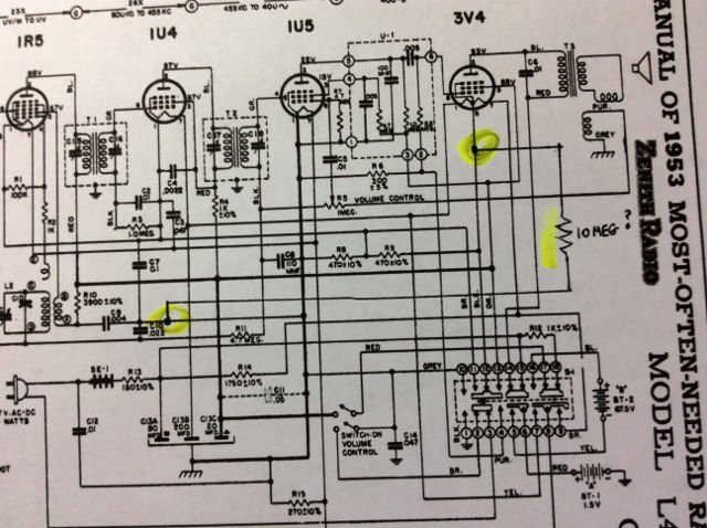
   

Did I mention that the radio plays okay?  There is a 10 Meg resistor inside U-1, a couplate unit.  I could understand if the 10 meg addition were soldered in at pin 2 of the 1U5 and pin 3 of the 3V4.  It would indicate that a technician had concluded the 10M in the copulate was bad, but that isn't where it's soldered in.  My aunts had this radio for years, used it daily with no complaints. I am less complacent.  Any ideas?  Thanks,  Joe

Joe

Matthew 16:26 "For what does it profit a man if he gain the whole world, yet lose his own soul?"
#2

The way you show it (not obvious) it's lower end goes to the chassis.
Why? Dunno, maybe improves on hum. Or slide switch scratch when it is slid.

People who do not drink, do not smoke, do not eat red meat will one day feel really stupid lying there and dying from nothing.
#3

Morzh,

You are absotively correct.  I have a head cold the size of Texas and am not thinking straight. Icon_crazy  The 10 Meg connection is one line under, between C10 and R11, and pin 5 of the 3V4.  Joe

Joe

Matthew 16:26 "For what does it profit a man if he gain the whole world, yet lose his own soul?"
#4

Finished!
   
Selenium Power Supply Before

   
Power Supply After.  I used a 1N5608, 3A 1KV rated diode, and a 200 ohm and an 82 ohm 5W resistor to compensate for the missing resistance of the selenium.  Voltage is about 1 volt higher than normal; no problem.

Cleaned and reassembled:


Joe

Matthew 16:26 "For what does it profit a man if he gain the whole world, yet lose his own soul?"
#5

Nice!

Out of curiosity, what about the 10meg resistor?

Crist
#6

(04-16-2015, 09:14 PM)ecstunter Wrote:  Nice!  

Out of curiosity, what about the 10meg resistor?

Thanks!  The 10 meg resistor belonged there.  Without it it was dead.  Apparently they left it out when drawing up the schematic.  Icon_crazy

Joe

Matthew 16:26 "For what does it profit a man if he gain the whole world, yet lose his own soul?"


Users browsing this thread: 1 Guest(s)
[-]
Recent Posts
The speaker table error?
G  10-1/2"       65, 76, 87, 95 Push-Pull 45's 2766 0.7 550 3200 H   10-1/2"    77, 96 Push-Pull...morzh — 09:26 PM
A Marconi model 86
I have a Stromberg, one of the early ones, seems early 30s. This is what I call a back breaker. None of the early Philc...morzh — 08:28 PM
A Marconi model 86
A backbreaker.....PaulPaul Philco322 — 08:12 PM
A Marconi model 86
>>What a behemoth! A Juggernaut.morzh — 07:47 PM
Philco 70 antenna lead
I am not sure I understood about the coils and the mush. I looked an more than one coil in 20, 70, 90, 60, Zeniths and ...morzh — 07:46 PM
A Marconi model 86
:e_biggrin: What a behemoth!  I hope the final result is as much a quality sounding example!  Keep us posted on your pro...GarySP — 07:32 PM
A Marconi model 86
I should add that the double conversion may only be used on the shortwave bands, but I haven't looked at the schematic t...Arran — 07:27 PM
Philco 70 antenna lead
Yes, that wire will not pick up much interference as routed - the RF at that level won't be affected, and if you have st...radio1 — 07:26 PM
Philco model 60
I'm also a member of MARC. Did you attend the Vintage Electronics Expo in Waterford, MI last month? That's where I got...GarySP — 07:22 PM
A Marconi model 86
Dan Double conversion is using two IF converters instead of one. This improves the image response. morzh — 07:15 PM

[-]
Who's Online
There are currently no members online.

>