10-14-2016, 11:03 AM
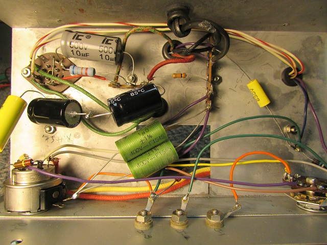
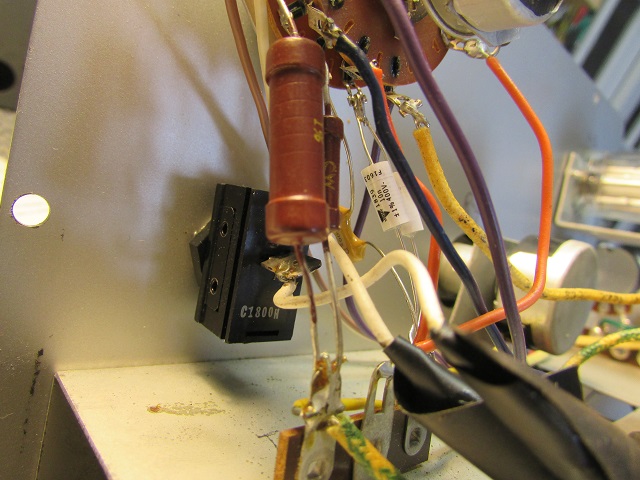
Work got crazy for the last month, so nothing got accomplished. I finally got back into the cap checker. I replaced the precision reference caps. Got them from Mouser. I had to parallel to get both my .02 and 2mf. Went ahead and replaced the mica so I would be sure it was good. In the picture below, note the small resistor to the right of the caps in series connected to the terminal strip. I used an empty lug to add the extra resistor into the voltage divider string.


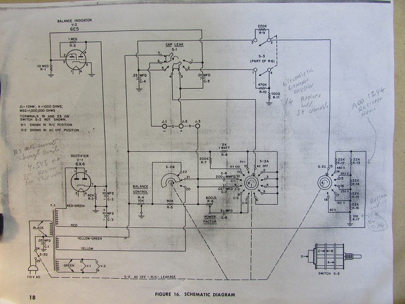
I have been following the write up I found at: http://tubesound.com/2008/08/23/rc-testers/ by Bob Putnak. I have been following his advice to set the voltage and current in the divider string. He said as wired, the voltages and currents were wrong (too high).

Mine checked high also, so I have been trying different values of resistors, mainly adding some resistance in the divider string. He recommended a 15.4k. I put in a 15k. He also said to adjust R3, the 82k. Mine was 92k. And, to replaced the R17 with 11k, from 10k. However, here is what I am discovering on mine. I had to set R3 to 56k to get the 4.5 Ma and put my my eye tube down around 180v. I left the R17 alone since it was 10.8k, and changing it didn't make much difference. I have my Ma meter between the new resistor (off C3 -) and where it goes to the voltage divider. Bob wasn't real clear where to connect. So far, I can get my current to around 4.48 and 4.55. My voltage is around 450 on the test terminals with leakage switch engaged. Also my Ma current increases when I switch this on. This seems very sensitive to line voltage variations, so I am setting it at 120v. From reading the write up, Bob says the current is pretty important. If I check the voltage right off the added resistor on the divider, then I get around -470v. Not super happy with this, so I am going to do some more experimenting.
I have been following the write up I found at: http://tubesound.com/2008/08/23/rc-testers/ by Bob Putnak. I have been following his advice to set the voltage and current in the divider string. He said as wired, the voltages and currents were wrong (too high).
Mine checked high also, so I have been trying different values of resistors, mainly adding some resistance in the divider string. He recommended a 15.4k. I put in a 15k. He also said to adjust R3, the 82k. Mine was 92k. And, to replaced the R17 with 11k, from 10k. However, here is what I am discovering on mine. I had to set R3 to 56k to get the 4.5 Ma and put my my eye tube down around 180v. I left the R17 alone since it was 10.8k, and changing it didn't make much difference. I have my Ma meter between the new resistor (off C3 -) and where it goes to the voltage divider. Bob wasn't real clear where to connect. So far, I can get my current to around 4.48 and 4.55. My voltage is around 450 on the test terminals with leakage switch engaged. Also my Ma current increases when I switch this on. This seems very sensitive to line voltage variations, so I am setting it at 120v. From reading the write up, Bob says the current is pretty important. If I check the voltage right off the added resistor on the divider, then I get around -470v. Not super happy with this, so I am going to do some more experimenting.
If I could find the place called "Somewhere", I could find "Anything"
Tim
Jesus cried out and said, "Whoever believes in me , believes not in me but in him who sent me" John 12:44


![[-] [-]](https://philcoradio.com/phorum/images/bootbb/collapse.png)


