09-21-2021, 04:43 PM
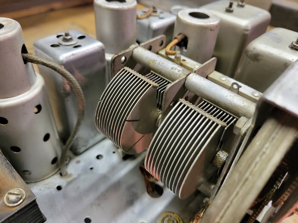
Thanks, Mike. I gave the tuning capacitor the once over and the fins look nice and straight and don't appear to be binding anywhere. I'll check it with the multimeter but there is no discernible "click" or "pop" or crackle as you tune that would indicate one "fin" was touching another. Just so it makes more sense, this is the tuning capacitor with the radio playing beautifully at 620 AM, the strongest Milwaukee station some 40 miles away.

And this is the tuning capacitor with the radio playing beautifully at 1470 AM the strong station here in West Bend.

That one appears to be correct. And I get all of the local stations in between 620 and 1470....just that it's on half of the rotation of the tuning cap. I'm beginning to wonder, since this is a 3 band radio and only a two gang tuner if they somehow isolated part of the broadcast band for the police band? The Shortwave band has full range of motion, meaning stations can be heard all across the rotation from fully meshed to fully open.
I had the Grunow set at 620 AM and tried the local OSC test with another AM radio and could not find the signal at either 465 (or 490) above on the test radio.
I did take some voltage readings on the 3 tubes involved in the RF section:
6A7
Pin 2 Plate should be 245v, I had 266
Pin 3 SG should be 85v, I had 83
Pin 4 G2 should be 190v, I had 206
Pin 5 Cathode should be 4.5v, I had 3.3
Grid cap read (negative) -1.9v
6D6
Pin 2 Plate should be 230v, I had 269
Pin 3 SG should be 80v, I had 83
Pin 4 G2 & Pin 5 cathode, shows 2.5v combined. I had 1.3 volts on each pin 4 & 5
75
Pin 2 Plate should be 90v, I had 95
Pin 5 Cathode should be 1v, I had 1v
This one has me stumped.
And this is the tuning capacitor with the radio playing beautifully at 1470 AM the strong station here in West Bend.
That one appears to be correct. And I get all of the local stations in between 620 and 1470....just that it's on half of the rotation of the tuning cap. I'm beginning to wonder, since this is a 3 band radio and only a two gang tuner if they somehow isolated part of the broadcast band for the police band? The Shortwave band has full range of motion, meaning stations can be heard all across the rotation from fully meshed to fully open.
I had the Grunow set at 620 AM and tried the local OSC test with another AM radio and could not find the signal at either 465 (or 490) above on the test radio.
I did take some voltage readings on the 3 tubes involved in the RF section:
6A7
Pin 2 Plate should be 245v, I had 266
Pin 3 SG should be 85v, I had 83
Pin 4 G2 should be 190v, I had 206
Pin 5 Cathode should be 4.5v, I had 3.3
Grid cap read (negative) -1.9v
6D6
Pin 2 Plate should be 230v, I had 269
Pin 3 SG should be 80v, I had 83
Pin 4 G2 & Pin 5 cathode, shows 2.5v combined. I had 1.3 volts on each pin 4 & 5
75
Pin 2 Plate should be 90v, I had 95
Pin 5 Cathode should be 1v, I had 1v
This one has me stumped.
Greg V.
West Bend, WI
Member WARCI.org


![[-] [-]](https://philcoradio.com/phorum/images/bootbb/collapse.png)


