Welcome Guest! Be sure you know and follow the Phorum Rules before posting. Thank you and Enjoy! (January 12) x

Thread Closed
Thread Rating:
  • 0 Vote(s) - 0 Average
  • 1
  • 2
  • 3
  • 4
  • 5

Philco 40-95 Farm Set
#13

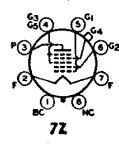
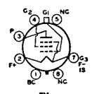
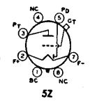
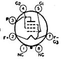
The RCA receiving Tube Manual (RC14) would be your best source for pin diagrams.  These diagrams are usually "worm's eye" view (underside of chassis) as opposed to "bird's eye view" from above chassis.  The base diagrams for the 1A7 Convertor, 1N5 IF and 1H5 Detector / 1st AF are reproduced below.  The diagrams for the various output tubes are in my previous post.  Try to score a 1Q5 instead of the 3Q5, as the base diagram for the 1Q5 is the same as all of the other output tubes available except the 3Q5.

The following are helpful tips.  
  • Print a copy (or several copies) of the schematic diagram from either the Philco Library on this site or the Nostalgia Air site.  Write the pin numbers from the attached tube base diagrams onto the schematic.  This should be fairly easy for all tubes except the convertor.
  • 22 gauge wire would be sufficient for all connections, although 20 gauge would be better for the filaments and battery connections.
  • Pin 7 of each tube is the filament (cathode) connection to the chassis (A- and B-) Pin 2 is the A+ connection to the filament.  Pin 3 is usually the plate (or main plate in multi-function tubes like diode / triode).  Pin 4 is usually the screen grid.  For the Output tube, Pin 5 is the control (or signal input) grid.  For the other tubes, the grid cap is for the control (or convertor signal input) grid.  For the 1N5 IF and 1A5, etc. Output tubes, the suppressor grid (or beam plates) are tied to the filament at pin 7.
  • I am not sure what colors were used by Philco in this time frame, but most post war radios used red or orange for B+, blue for the plate connection to a transformer, green or yellow for a grid, black for wires going to the chassis, white for AVC and for negative bias. This may not be true for pre-war Philcos.  Maybe any expert who has a pre-war Philco using these tubes can take pictures.  The colors are not important unless you are building a museum quality restoration (and based on the condition of the case, you may choose to do so.
  • The IF transformers should be around 15-20 Ohm for primary and secondary.  On my RCA 14BT2, same vintage as the Philco that you are working on, Plate for these transformers is blue, B+ is red, Grid or detector diode plate is green and AVC or audio out is black.
  • Build backwards!  Build and test the Audio Output and the Detector / 1st Audio.  Then build the IF.  Finally, build the convertor stage.  If you have a signal generator, you can test the stages as they are built.
  • This set will require an antenna and ground wire.  Alternately, you can replace the antenna coil with a loopstick, but you will have to peak the trimmer on the RF section of the tuning condenser.
  • Good luck!

Diagrams below:

1A7 Convertor:
   

1N5 IF Amp
   

1H5 Det / 1St AF Amp
   

1A5, 1C5, etc Output (1Q5 same)
   

"Do Justly, love Mercy and walk humbly with your God"- Micah 6:8
"Let us begin to do good"- St. Francis

Best Regards, 

MrFixr55


Messages In This Thread
Philco 40-95 Farm Set - by 7chip7 - 01-05-2024, 01:27 PM
RE: Philco 40-95 Farm Set - by Radioroslyn - 01-05-2024, 04:14 PM
RE: Philco 40-95 Farm Set - by klondike98 - 01-05-2024, 04:15 PM
RE: Philco 40-95 Farm Set - by 7chip7 - 01-05-2024, 06:53 PM
RE: Philco 40-95 Farm Set Case - by 7chip7 - 01-05-2024, 07:08 PM
RE: Philco 40-95 Farm Set - by 7chip7 - 01-06-2024, 04:49 PM
RE: Philco 40-95 Farm Set - by Arran - 01-07-2024, 02:36 AM
RE: Philco 40-95 Farm Set - by David - 01-07-2024, 03:10 PM
RE: Philco 40-95 Farm Set - by MrFixr55 - 01-07-2024, 08:39 PM
RE: Philco 40-95 Farm Set - by 7chip7 - 01-08-2024, 10:36 AM
RE: Philco 40-95 Farm Set - by morzh - 01-08-2024, 11:31 AM
RE: Philco 40-95 Farm Set - by 7chip7 - 01-08-2024, 11:57 AM
RE: Philco 40-95 Farm Set - by MrFixr55 - 01-08-2024, 01:04 PM
RE: Philco 40-95 Farm Set - by 7chip7 - 01-08-2024, 03:14 PM
RE: Philco 40-95 Farm Set - by MrFixr55 - 01-08-2024, 07:43 PM
RE: Philco 40-95 Farm Set - by MrFixr55 - 01-08-2024, 07:46 PM
RE: Philco 40-95 Farm Set - by MrFixr55 - 01-08-2024, 08:51 PM
RE: Philco 40-95 Farm Set - by David - 01-08-2024, 09:18 PM
RE: Philco 40-95 Farm Set - by Radioroslyn - 01-09-2024, 12:25 AM
RE: Philco 40-95 Farm Set - by 7chip7 - 01-09-2024, 04:22 PM
RE: Philco 40-95 Farm Set - by David - 01-09-2024, 06:52 PM
RE: Philco 40-95 Farm Set - by RodB - 01-09-2024, 07:27 PM
RE: Philco 40-95 Farm Set - by Radioroslyn - 01-09-2024, 07:29 PM
RE: Philco 40-95 Farm Set - by Arran - 01-09-2024, 09:20 PM
RE: Philco 40-95 Farm Set - by 7chip7 - 01-10-2024, 11:22 AM
RE: Philco 40-95 Farm Set - by 7chip7 - 01-10-2024, 02:44 PM
RE: Philco 40-95 Farm Set - by Radioroslyn - 01-10-2024, 03:08 PM
RE: Philco 40-95 Farm Set - by 7chip7 - 01-11-2024, 04:45 PM
RE: Philco 40-95 Farm Set - by Arran - 01-13-2024, 03:39 AM
RE: Philco 40-95 Farm Set - by 7chip7 - 01-13-2024, 04:52 PM
RE: Philco 40-95 Farm Set - by David - 01-13-2024, 05:22 PM
RE: Philco 40-95 Farm Set - by 7chip7 - 01-17-2024, 02:46 PM
RE: Philco 40-95 Farm Set - by David - 01-17-2024, 10:07 PM
RE: Philco 40-95 Farm Set - by 7chip7 - 01-18-2024, 02:09 PM
RE: Philco 40-95 Farm Set - by 7chip7 - 01-19-2024, 01:54 PM
RE: Philco 40-95 Farm Set - by MrFixr55 - 01-27-2024, 11:28 PM
RE: Philco 40-95 Farm Set - by MrFixr55 - 01-27-2024, 11:36 PM


Users browsing this thread: 7 Guest(s)
[-]
Recent Posts
The list of my radio & TV collection!
Hello Peter, Thank you for posting that !! Sincerely Richardradiorich — 09:40 AM
Eico 232 VTVM Schematic
It's a microwave antenna. ?;-p?. I substituted 1N4002s off the 6.3 vac winding for the 1.5 volt battery. Uniprobe is the...RodB — 05:50 PM
Eico 232 VTVM Schematic
Try BAMA for a schematic. Looks like a replacement power source for the D battery has been installed. The tube may be...Chas — 04:51 PM
Eico 232 VTVM Schematic
Is that a battery holder?morzh — 04:43 PM
Eico 232 VTVM Schematic
A friend gave me this Eico 232 VTVM and I'm having trouble locating the schematic for it. This one seems to be a later v...RodB — 04:17 PM
Var resistor id
Considering what it is in series with, I doubt there should be any power requirements. Of course, we should know wher...morzh — 03:23 PM
Var resistor id
Trim pot, about 1/2 watt part of focus divider. As stated 2k ohms. This appears to be a rusty chassis, resolder all ...Chas — 03:19 PM
Var resistor id
Its a Sylvania 400 oscilloscope. here is a clip of r-100. Would be nice to know the current required. Not listed in part...Martinj — 02:10 PM
The list of my radio & TV collection!
Thanks Richard. I hope you enjoy it. Here I have created an English section on the history of radio with videos in Engl...RadioSvit — 10:23 AM
The list of my radio & TV collection!
Hello RadioSvit, first all happy new year ! I will watch your new videos this week. Sincerely Richardradiorich — 09:19 AM

[-]
Who's Online
There are currently 7787 online users. [Complete List]
» 2 Member(s) | 7785 Guest(s)
AvatarAvatar

>