08-10-2024, 07:23 PM
I mistyped the last sentence from the first paragraph of my last post. I meant to write, "I may encounter different results if I don’t proactively address the issue now."
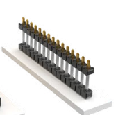
In any event, I have worked on a redesign in order for the two trimmer caps to be accessible while the can is in place. I have designed two PCBs, an upper and a lower. The lower board will comprise the majority of the system. It has connections 1, 2, 3, and 4 (one in each corner) for the four incoming/outgoing connections to the rest of the radio. It also has a space for the primary trimmer cap (to be mounted on the underside for access from the bottom of the chassis), the primary fixed capacitor, and both inductors. I have confirmed from experimentation that these two radial lead inductors need to stay side by side for best results. There are also four through-hole cut-outs for jumpers to the upper PCB. For both structural and electrical connection, I plan to use these vertical header pins which are used for connecting two stacked PCBs. I will only need two sets of single-row, double-pin connectors.

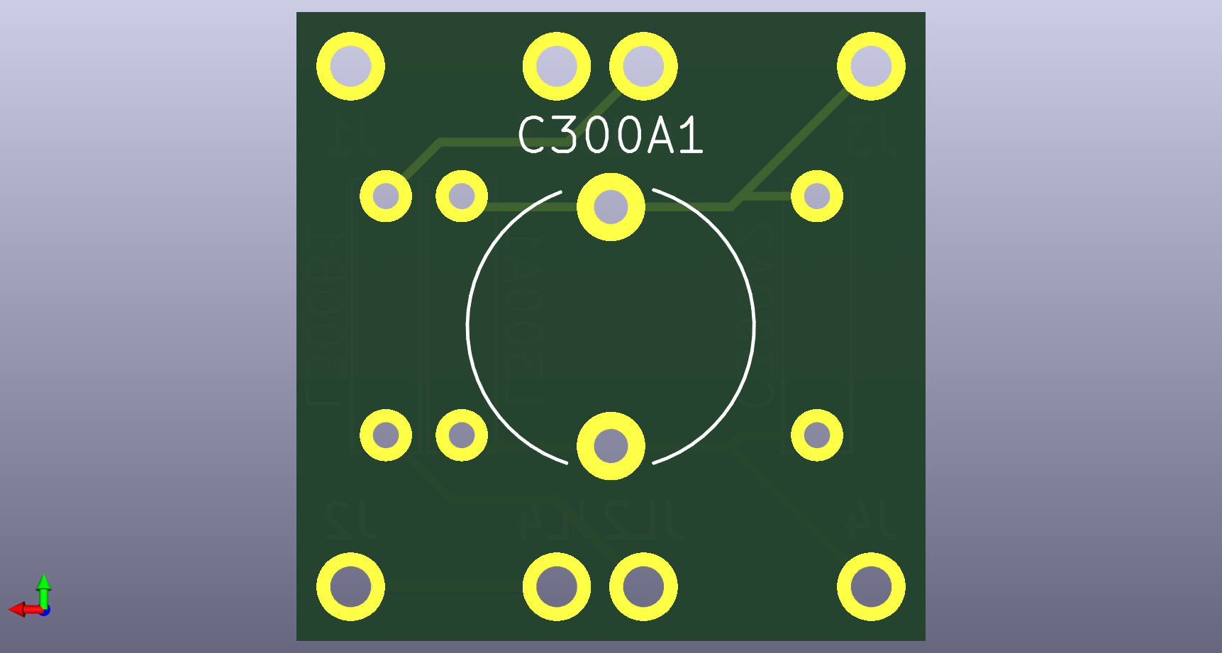
Here are top and bottom views of the lower PCB.


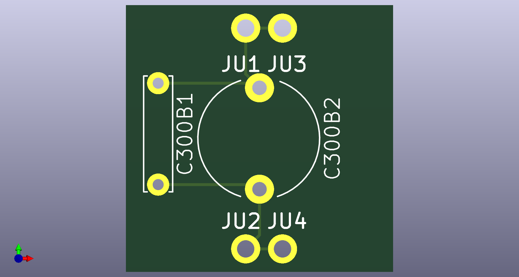
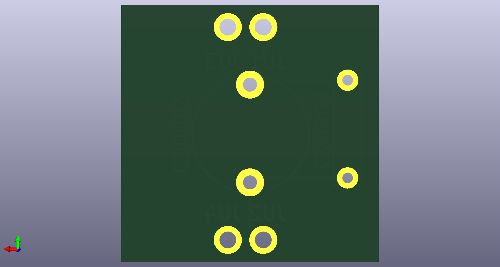
The upper PCB will consist of the secondary fixed capacitor and trimmer cap (centered and facing up for access from the top of the can). It features the same four through-hole cut-outs for soldering to the vertical header pins. Here are top and bottom views of the upper PCB.


For clarity, I have attached the two schematics for the upper and lower board.
In any event, I have worked on a redesign in order for the two trimmer caps to be accessible while the can is in place. I have designed two PCBs, an upper and a lower. The lower board will comprise the majority of the system. It has connections 1, 2, 3, and 4 (one in each corner) for the four incoming/outgoing connections to the rest of the radio. It also has a space for the primary trimmer cap (to be mounted on the underside for access from the bottom of the chassis), the primary fixed capacitor, and both inductors. I have confirmed from experimentation that these two radial lead inductors need to stay side by side for best results. There are also four through-hole cut-outs for jumpers to the upper PCB. For both structural and electrical connection, I plan to use these vertical header pins which are used for connecting two stacked PCBs. I will only need two sets of single-row, double-pin connectors.
Here are top and bottom views of the lower PCB.
The upper PCB will consist of the secondary fixed capacitor and trimmer cap (centered and facing up for access from the top of the can). It features the same four through-hole cut-outs for soldering to the vertical header pins. Here are top and bottom views of the upper PCB.
For clarity, I have attached the two schematics for the upper and lower board.
Joseph
Philco 46-480
Philco 49-906


![[-] [-]](https://philcoradio.com/phorum/images/bootbb/collapse.png)


