01-25-2025, 03:01 PM
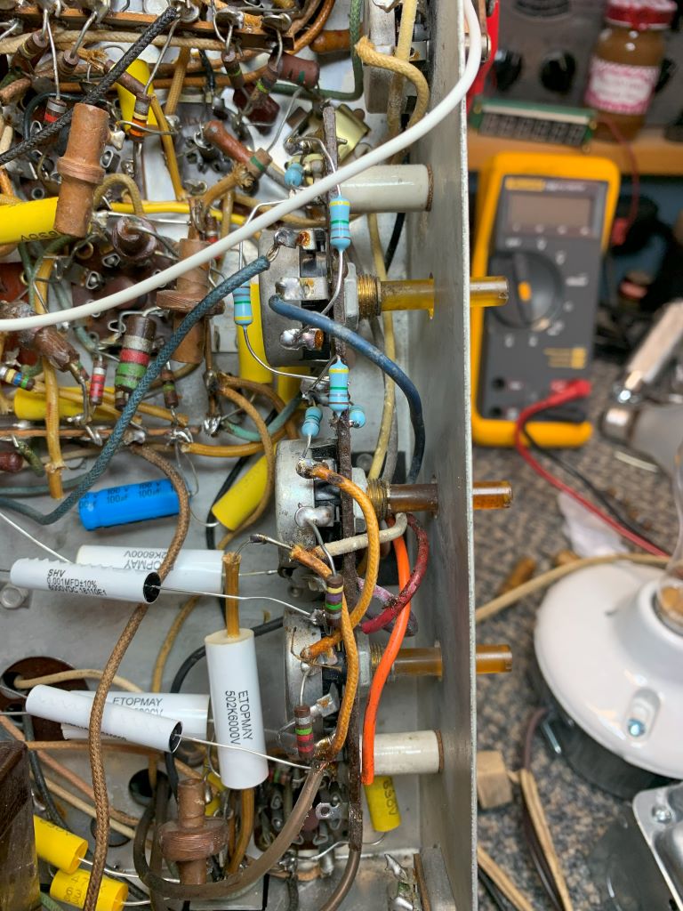
Update: While waiting on some NOS tube sockets for my amp experiment, I turned left and got back on the TV that was already occupying my bench, with parts laying nearby, still in the bags. In my previous power ups, I had a very limited vertical sweep, no horizontal at all. Poor focus and seemed the brightness would fade as I increased line voltage. After watching Mr. Anderson's video more than once, I replace the 1.8 meg resistors in the HV divider string. Then replaced the 2 10 meg resistors in the vertical output stage that connect to the coupling caps, which go to the deflection plates on the big tube. If you're following this thread, you will remember that one of those 2 10 meg resistors was open. It gave me slight deflection on the upper half of the screen. I also replaced the coupling capacitors on the H & V outputs, and the big HV cap that runs crossways. While I had things apart, I replaced the paper caps under the HV cage. I found that removing that big filter choke allowed easier access. Mose of those were soldered straight in and could simply heat, suck the solder, and pull out while heating. Some were bent and required some surgery. The picture below shows shows the replacement of the HV string resistors and the coupler caps. I do need to go back and replace a couple 22 meg resistors and insulate the hot side of the HV filter cap. I thought it was the low side until I got a little tingle and looked at the schematic!
Alright, now some pictures of the power up and what happened next!
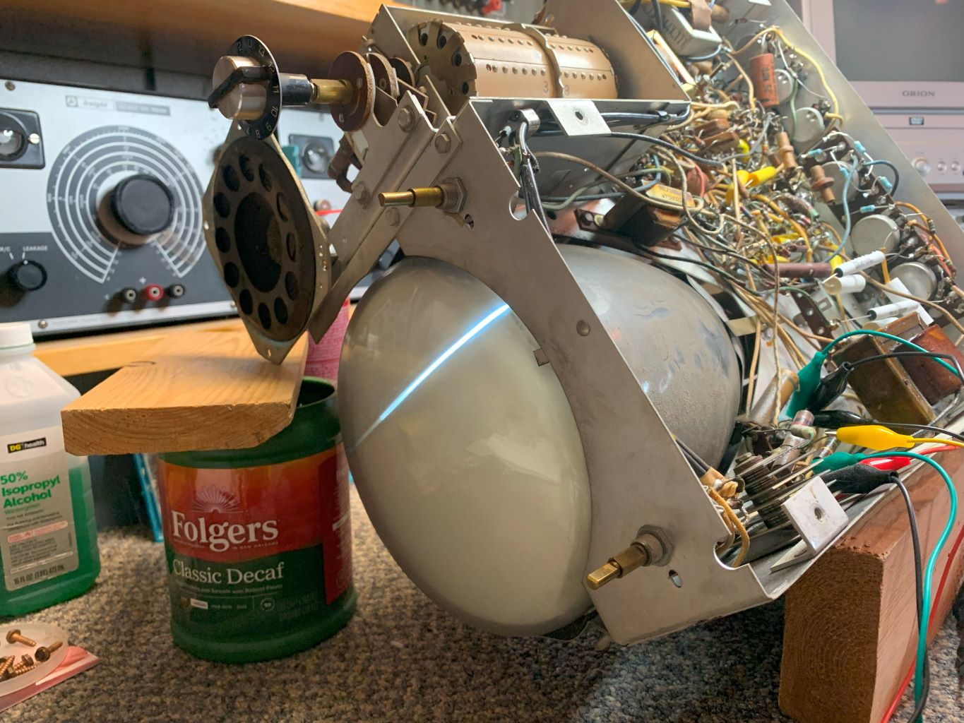
As you can see, I have full vertical deflection, but absolutely NO horizontal! I did find the focus and brightness controls worked through their range, you can see the sharp line. Huh. Why? So after some voltage checks and signal checks around the oscillator and output tube, I found I had NO plate or screen voltage on the output tube! After some tracing, I found B+ to the output trans, but nothing on the plate, screen or hot side of the coupling caps. Take a look at this circuit and you will soon see that this was NOT good news! Also note, this set does not use a common flyback as the more modern sets do. This is an electrostatic set. A whole different animal on the HV & deflection end.
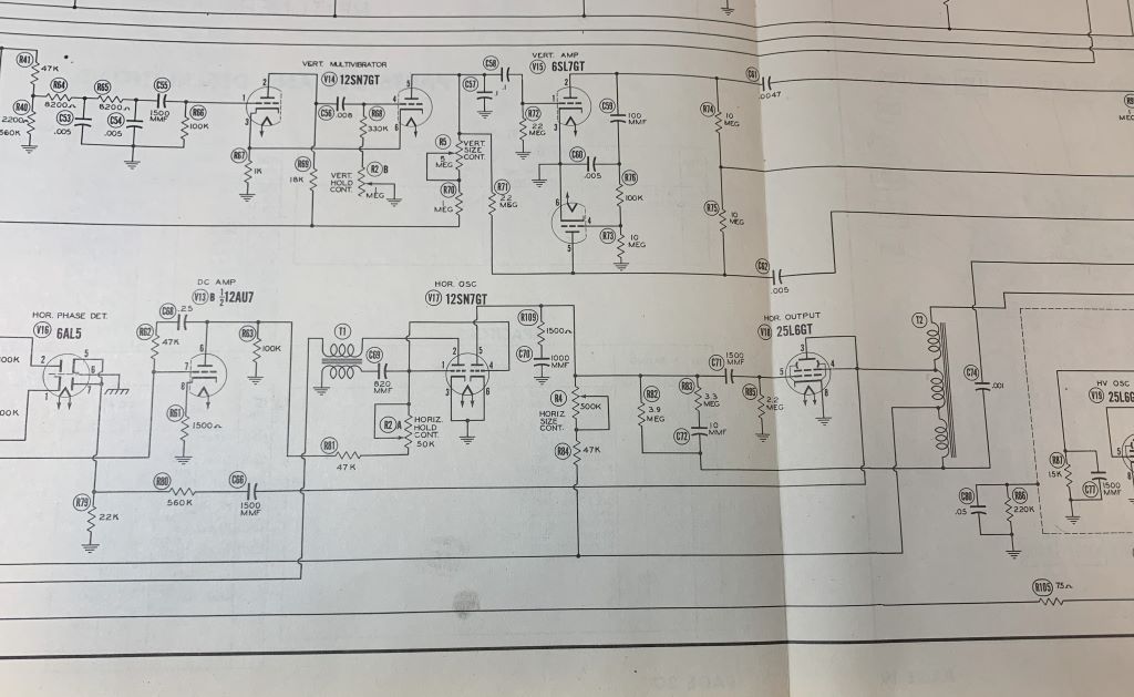
I did have a drive to the H out tube. Maybe not the best, (looks like it has some hum) but it was present, so a lack of signal didn't burn the transformer.
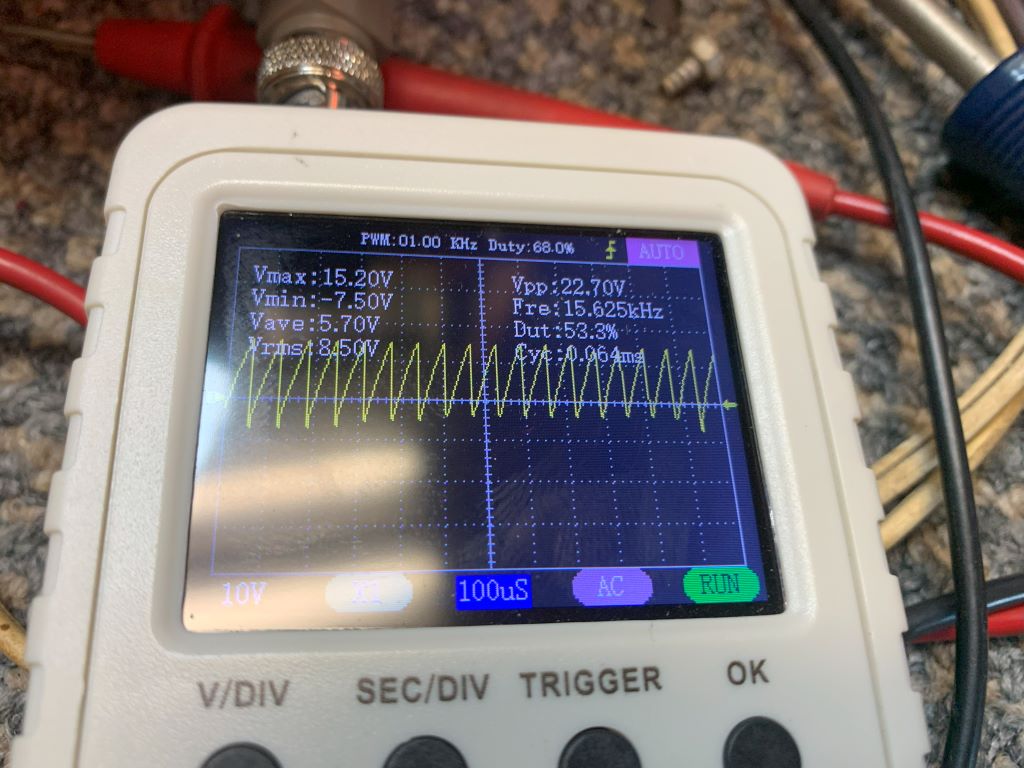
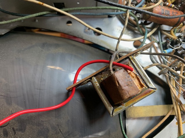
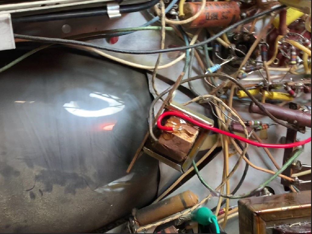
As you can see, the B+ goes through that transformer to the rest of the circuit. After the following checks, I found the there WAS continuity throughout the rest of the transformer! I checked from both ends, both ends to the plate lead, and had continuity. So, the only possible would be an open circuit from the B+ lead to the transformer. With this not exactly being something I could jump on AES or eBay and find, and knowing only about 1 person on this planet that would have one, I decided to try one last ditch effort at reviving it. I pulled it and wiggled the wires like a madman, with no results. Next, came out the surgical tools. Thankfully, this winding was accessible with only having to cut through a few layers. It wasn't broken. I CAREFULLY scraped the wires near the connection and applied the meter probe. You can imagine my delight when I saw my meter register a solid 39R! This thing has life! It looked like either bad solder or maybe corroded. I replaced the wire and all. The next pictures show the repair.
Alright, now some pictures of the power up and what happened next!
As you can see, I have full vertical deflection, but absolutely NO horizontal! I did find the focus and brightness controls worked through their range, you can see the sharp line. Huh. Why? So after some voltage checks and signal checks around the oscillator and output tube, I found I had NO plate or screen voltage on the output tube! After some tracing, I found B+ to the output trans, but nothing on the plate, screen or hot side of the coupling caps. Take a look at this circuit and you will soon see that this was NOT good news! Also note, this set does not use a common flyback as the more modern sets do. This is an electrostatic set. A whole different animal on the HV & deflection end.
I did have a drive to the H out tube. Maybe not the best, (looks like it has some hum) but it was present, so a lack of signal didn't burn the transformer.
As you can see, the B+ goes through that transformer to the rest of the circuit. After the following checks, I found the there WAS continuity throughout the rest of the transformer! I checked from both ends, both ends to the plate lead, and had continuity. So, the only possible would be an open circuit from the B+ lead to the transformer. With this not exactly being something I could jump on AES or eBay and find, and knowing only about 1 person on this planet that would have one, I decided to try one last ditch effort at reviving it. I pulled it and wiggled the wires like a madman, with no results. Next, came out the surgical tools. Thankfully, this winding was accessible with only having to cut through a few layers. It wasn't broken. I CAREFULLY scraped the wires near the connection and applied the meter probe. You can imagine my delight when I saw my meter register a solid 39R! This thing has life! It looked like either bad solder or maybe corroded. I replaced the wire and all. The next pictures show the repair.
If I could find the place called "Somewhere", I could find "Anything"
Tim
Jesus cried out and said, "Whoever believes in me , believes not in me but in him who sent me" John 12:44


![[-] [-]](https://philcoradio.com/phorum/images/bootbb/collapse.png)


