05-25-2015, 10:15 AM
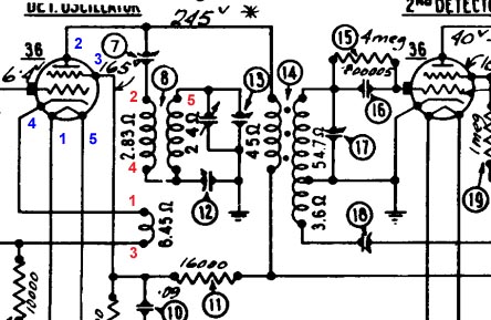
I am working on a Philco Model 80 Junior, and I have a couple questions about the oscillator coil, part number 8.
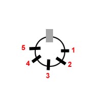
I measure continuity among pins 2-4-5, and between pins 2-4, and between pins 4-5. The tickler coil, pins 1-3 is open.


I pulled the coil out of the radio and removed the tickler portion. My question is about the primary and secondary. The outer coil appears to be larger wire, maybe 50 turns of 32 ga wire. It is wound on top of an inner coil or much finer wire, maybe 150 turns of 38 ga wire. This is all a guess.
The outer coil seems to be wired to pins 5 and 4. It measures 5 ohms. The inner coil is wired to pins 2 and 4. It measures 17 ohms. This resistance measurements don't match the schematic exactly, though relatively, 5 ohms is close to 2.83 and 17 ohms is closed to 24.
Question 1. Based on the resistance readings, doesn't this seem to indicate that the outer coil is the primary (left side) and the inner coil is the secondary (right side)? If that is the case, the coil is wired into the circuit backwards!
I am hoping someone has enough familiarity with this coil to help me make a judgement. What is wierd is that it appears to be original factory connections, not messed with. But who knows?
Question 2. Also, the tickler coil appeared to be 18 turns of maybe 34 ga wire, wound counter-clockwise looking from the bottom of the coil. I think that is what I observed. But my mind is playing tricks on me at this point. (I know, I need to be more careful). Does anyone know this tickler winding? Can you confirm?
Thanks!
Mark K8KZ
I measure continuity among pins 2-4-5, and between pins 2-4, and between pins 4-5. The tickler coil, pins 1-3 is open.
I pulled the coil out of the radio and removed the tickler portion. My question is about the primary and secondary. The outer coil appears to be larger wire, maybe 50 turns of 32 ga wire. It is wound on top of an inner coil or much finer wire, maybe 150 turns of 38 ga wire. This is all a guess.
The outer coil seems to be wired to pins 5 and 4. It measures 5 ohms. The inner coil is wired to pins 2 and 4. It measures 17 ohms. This resistance measurements don't match the schematic exactly, though relatively, 5 ohms is close to 2.83 and 17 ohms is closed to 24.
Question 1. Based on the resistance readings, doesn't this seem to indicate that the outer coil is the primary (left side) and the inner coil is the secondary (right side)? If that is the case, the coil is wired into the circuit backwards!
I am hoping someone has enough familiarity with this coil to help me make a judgement. What is wierd is that it appears to be original factory connections, not messed with. But who knows?
Question 2. Also, the tickler coil appeared to be 18 turns of maybe 34 ga wire, wound counter-clockwise looking from the bottom of the coil. I think that is what I observed. But my mind is playing tricks on me at this point. (I know, I need to be more careful). Does anyone know this tickler winding? Can you confirm?
Thanks!
Mark K8KZ


![[-] [-]](https://philcoradio.com/phorum/images/bootbb/collapse.png)


