Philco 70 restoration attempt - singing now.
Posts: 16,298
Threads: 567
Joined: Oct 2011
City: Jackson
State, Province, Country: NJ
Before proceeding I decide to test transformer, as it had some rust on top of the core and all.
So I just measured the AC between the rectifier anodes and then the filament voltage. All is OK.
Posts: 1,196
Threads: 83
Joined: Jan 2014
City: Annapolis, IL
State, Province, Country: USA
Good pic! Thanks Mike! I havent pulled the open coil on my 70 yet, but seeing this helps me know what to expect and how to repair. This must be a very common problem on these radios. I'll try to get mine pulled out this weekend.
If I could find the place called "Somewhere", I could find "Anything" 
Tim
Jesus cried out and said, "Whoever believes in me , believes not in me but in him who sent me" John 12:44
Posts: 16,298
Threads: 567
Joined: Oct 2011
City: Jackson
State, Province, Country: NJ
OK, now to recap.
Took me whopping 15 minutes to take out all the backelite block's stuffing out (6 of them).
I used that new approach I described in 90 thread - I only bite off the wires that connect the stuffed caps to the lugs and then without unscrewing the blocks heat them and push the contents out, which they seem to accept very happily. It is enough to heat 10 second each side of the backelite block on LOW setting and then push it with a small allen wrench.
Then I unscrew them and pull the contents out. If it is stuck a little (could be) - 5 seconds with LOW setting is enough to losen it.
Now Restuffing, then the electrolytics. I think I will not be getting to the lytics untill late tonight (well, I have a life  and a family of 4) or early tomorrow.
Posts: 16,298
Threads: 567
Joined: Oct 2011
City: Jackson
State, Province, Country: NJ
Attn: Tim!
The schematic has a discrepancy (not really a mistake):
There are two backelite cap blocks, #5 and #12, and they are the same, 0.09uF dual caps.
Now the sch shows the wiper of the volume pot section going to G and F voltages going to a cap in #5, and the oscillator Cathode going to #12 cap (G voltage).
In fact the caps are swapped.
The functionality is the same.
Posts: 16,298
Threads: 567
Joined: Oct 2011
City: Jackson
State, Province, Country: NJ
Now,
Have just finished the last backelite block.
Plus some resistors plus the new chord.
Need to buy a new panel for the 47 tube as it's been replaced as I mentioned before.
Have to go shopping for the panel. If anyone has good ideas where to buy one, suggestions are welcome.
PS. Never mind, have just bought it for $3.70 plu shipping on eBay. Ok, I will have a chinese part in the radio. Screw it, the caps are chinese also no matter how you hide'em. 
Posts: 16,298
Threads: 567
Joined: Oct 2011
City: Jackson
State, Province, Country: NJ
Today finished resistors (ell I only replaced two, one is not critical and did not go far, and one went up went up 20% so I put a resistor in parallel (can't be seen) so it is where it should be and looks good too.
Rebuilt the tin can caps, took me under 30 minutes for two of them.
And rebuilt the tone control.
here are photos. This one is easy - just one cap.
The first look - even though I vacuumed the chassis, on top of this one there were still some of those broom corn seeds.
And the wire is in dismal shape also.
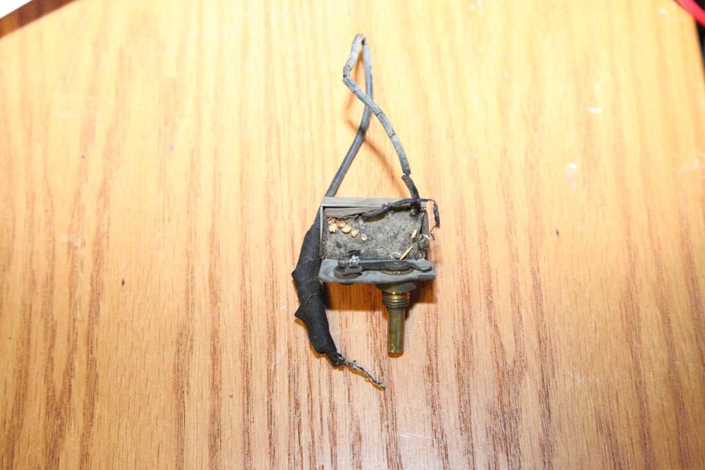
Took the tarred part out, here is the paper and the can.
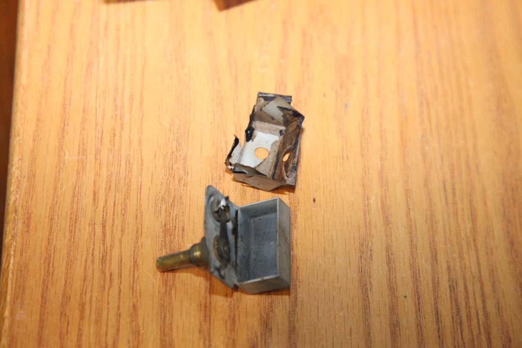
Now put the paper back.
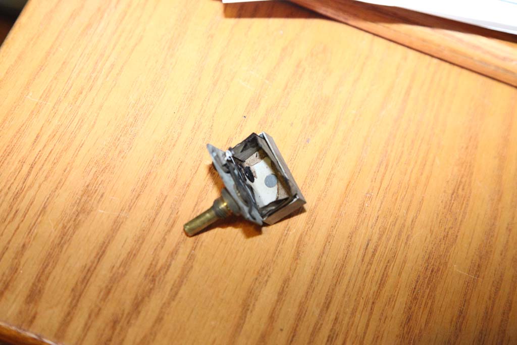
Insert the cap, solder the leads and pot.

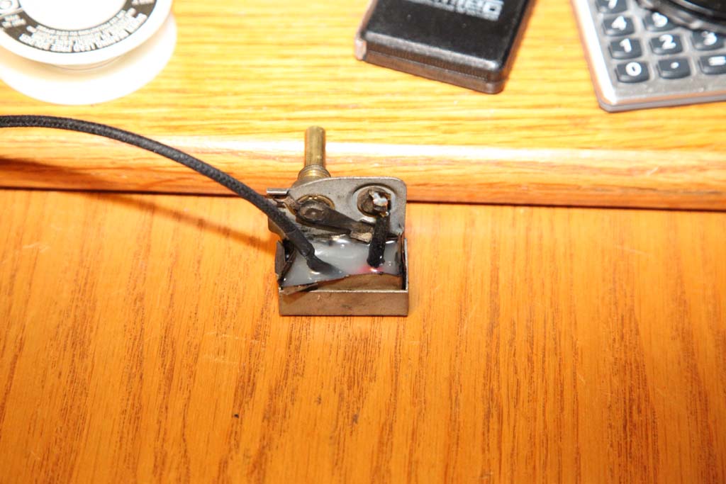
Posts: 16,298
Threads: 567
Joined: Oct 2011
City: Jackson
State, Province, Country: NJ
A note:
Measured that inductance in the RF filter in the 2nd detector in the plate circuit. I was interested in it because it should be the same as in 90's detector and I did not know the value.
Well, for those interested: it is 11mH and the DC resistance is 100 Ohm.
The L-meter also gives me Q factor equal about 21 (not that I think it is important here).
As for the plate detector circuit itself, I wonder why Philco variated some values so much. They might not even be important values, but I always thought reusing the values is a good thing, cuts the inventory down.
For instance, in the 90 using the same tube and, I presume, close plate power voltages, the resistor for the screen grid of the 2nd detector is 250K which is then filtered by a fairly large cap.
In 70 the exact same screen grid in practically the same plate detector is 250 Ohm, and then also filtered by a cap of the same order of value.
I did not have 250 Ohms resistor and I do not think it matters so I simply put 1K there or something.
Posts: 4,106
Threads: 310
Joined: Nov 2013
City: Kings Park NY
Ok, I understood all of that. Not!
I guess I have to check the pot to see if I missed a cap.
Very nice work and thanks for the step by step
Times I have been electrocuted in 2021
As of 1/01/2021
AC: 4 DC: 1
Last year: 6
Posts: 16,298
Threads: 567
Joined: Oct 2011
City: Jackson
State, Province, Country: NJ
Today spent a whole lot more time than it should be to gut the two electrolytics.
Oh, Geez! The first was a real bear to get the guts out but then the cleanup was quick.
The second (same exact cap) allowed very quicly to take part of it oiut (the cylinder separated in two) but the taking out the rest was a real b...ch.
Usually the aluminum caps are not that bad at all.
Will restuff them tomorrow, I cannot even look at them anymore.
Once done, the restoration of the output tube with the new panel will be the last piece of the puzzle (oh, and of course putting the tuning cap back) and then....you got it, power up.
5-pin tube panel, come to papa! Come quick!
Posts: 16,298
Threads: 567
Joined: Oct 2011
City: Jackson
State, Province, Country: NJ
Hit a little snag - the 5-pin tube panel that came in today, though is right for the tube (47) but wil not install unless I drill two extra holes and I am not crazy about drillin anything at all.
The screw / rivet holes are perfectly symmetrical in this one and Philco's are off-center.
I'd rather have a Philco one.
I placed an ad in WTB and a separate threacd here in case someone has a spare.
BTW wanted to ask - when installing these, short of screwing it are there rivets that could be used? Regular rivets will break the panel if attempted - the material is brittle. Screws look wrong though i will use them at least temporarily if have to.
Posts: 16,298
Threads: 567
Joined: Oct 2011
City: Jackson
State, Province, Country: NJ
An example of a simplified electrolytic re-stuff.
The wires are not insulated - they are fairly rigid and will be held by being potted with hot glue.
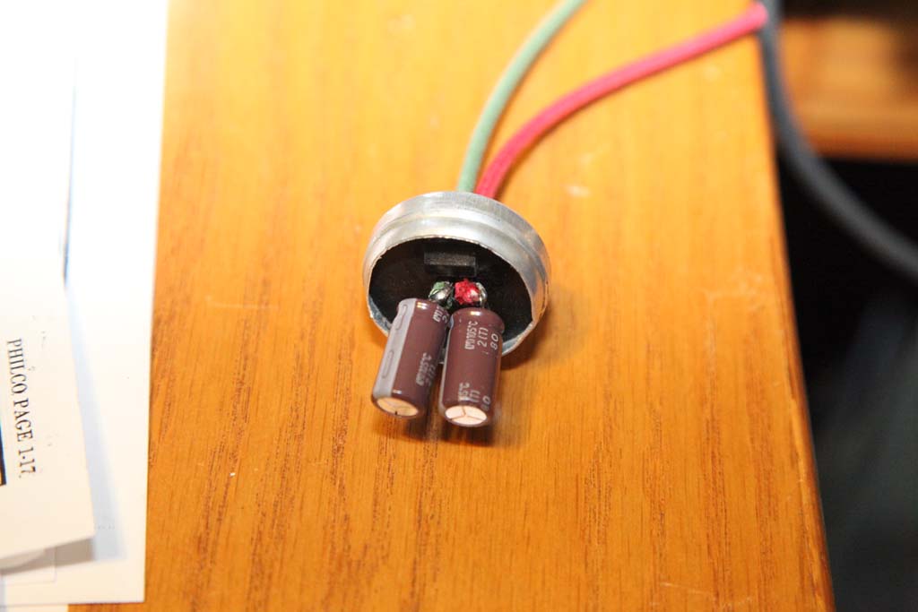
The other side (where the capacitors serialize)
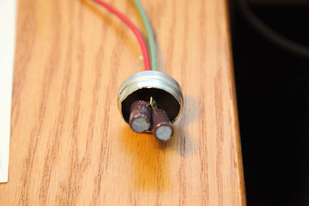
Potted
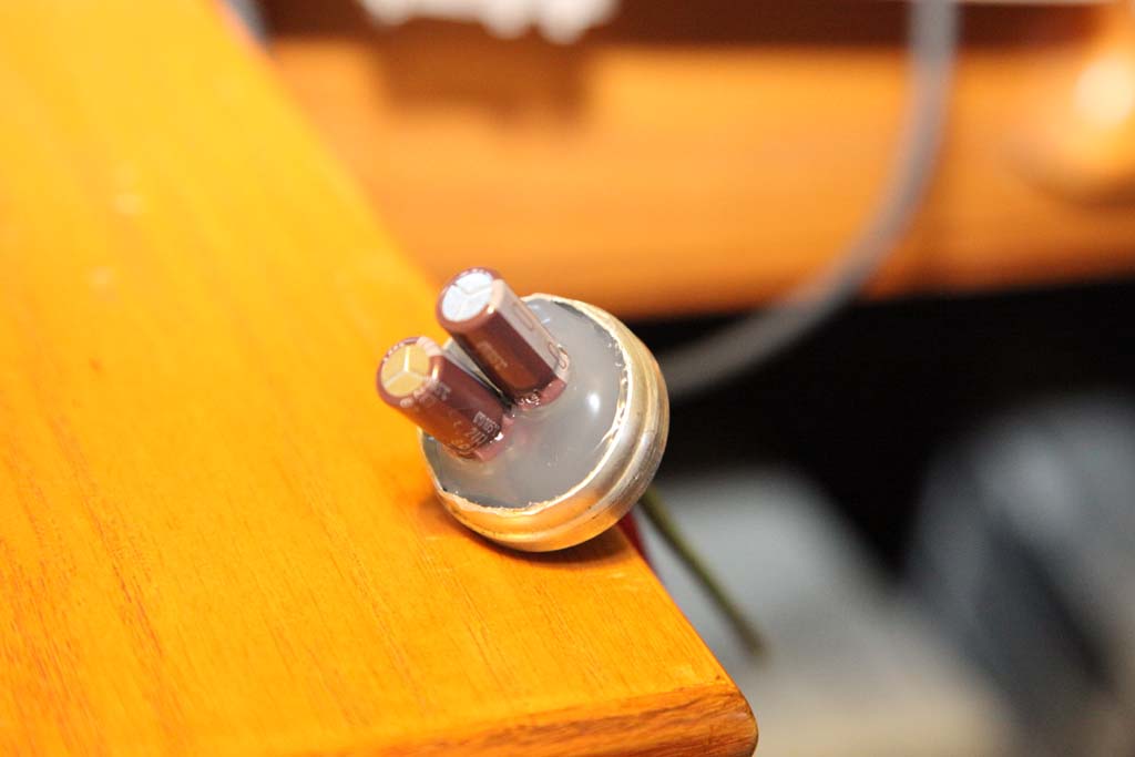
The wires coming out
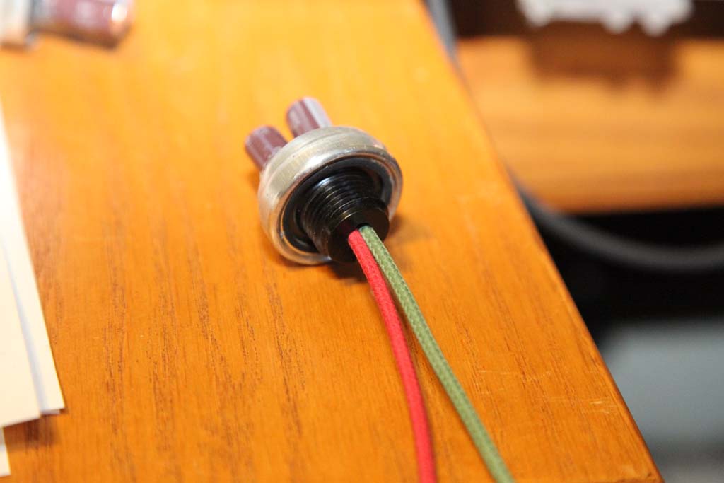
I had to widen the hole in the base - the wires are fairly fat.
This is why I did not have to insulate the wires with heat shrink or tape - they are far enough apart and then the hot glue will get in between so it is secure.
Posts: 4,106
Threads: 310
Joined: Nov 2013
City: Kings Park NY
Looking nice,
I haven't tried the hot glue but with the Halson I do want to restuff those 2 big cardboard Ecap tubes.
You need more pictures so I understand it better, plus I like pictures anyway. 
Cant wait till its done! keep on going and keep us updated.
Times I have been electrocuted in 2021
As of 1/01/2021
AC: 4 DC: 1
Last year: 6
Posts: 16,298
Threads: 567
Joined: Oct 2011
City: Jackson
State, Province, Country: NJ
Kirk
It is simple: you twist the two wires (+ and -) of the two caps together, cut the twist short and solder them together.
Bend it out (so it does not get bent on its own the way it wants when pressed against the base).
Then you bend the other wires (plus and minus) into short loops, bend them in the opposite direction from the twist (to create more space), thread red (plus) and black (or green/blue/whatever it is you like for the minus) wires through the loops and solder them. (Trim if necessary and touch up with some solder so no bare copper is exposed.)
Then you draw the wires through the hole in the base and pull them until the caps are close to to it, like on the photo.
Watch for the wires being apart and apart from the twist.
There will be some space left between the bottom of the caps and the base.
This is where you start hot-gluing, letting the plastic fill the spaces - this will keep it stable and insulated.
Then you fill the whole base with the plastic.
Let it freeze, and this is it.
Posts: 669
Threads: 145
Joined: Jun 2011
City: Elko,MN.
OOFTA!!!!!!!!!!!!!!!!!!!!!!!!!
Posts: 16,298
Threads: 567
Joined: Oct 2011
City: Jackson
State, Province, Country: NJ
Murf
tust me it is simple if you know what to do. Very simple. Opening and cleaning is the less enjoyable part, but stuffing is a breeze.
Users browsing this thread: 3 Guest(s)
|
|
Recent Posts
|
|
Philco model 60
|
| Yes, Mark belongs to the same Michigan Antique Radio Club that I do. I suspect that the oscillator coil is in need of a ...Radios1340 — 03:10 PM |
|
A Marconi model 86
|
| Yeah. I am dreading the thought of what to do with all my consoles when I will no longer be able to move them around.
I...morzh — 02:51 PM |
|
1947 Silvertone 7086 Wire Recorder/Phono/Radio on YouTube
|
| Cool gadget, Buzz.
I took me a couple of second to undestand that that oscillating thing makes the wire to spool correc...morzh — 02:50 PM |
|
A Marconi model 86
|
| My back hurts already, you could build a house with all the wood. PaulPaul Philco322 — 02:49 PM |
|
1947 Silvertone 7086 Wire Recorder/Phono/Radio on YouTube
|
| Part 4 of this series now uploaded
link below to anyone interested
Buzz — 02:39 PM |
|
Philco model 60
|
| Welcome to the Phorum, Radios1340! The oscillator coil on the 60 is a common culprit. I just bought a 60B (June 1934) ...GarySP — 02:33 PM |
|
Philco model 60
|
| Yes, standard alignment procedure. I can get the minuscule tone to vary when adjusting the trimmers. But you almost have...Radios1340 — 01:40 PM |
|
A Marconi model 86
|
| An imposing-looking radio, for sure.morzh — 12:43 PM |
|
Philco model 60
|
| Model 60 struck again :lol:
Welcome to the Phorum!
Above is the article on Model 60. Could be of some use.
Now...morzh — 12:38 PM |
|
A Marconi model 86
|
| Ooh, very nice!jrblasde — 12:19 PM |
|
Who's Online
|
There are currently 6643 online users. [Complete List]
» 5 Member(s) | 6638 Guest(s)
|
|
|

|
 
|


![[-] [-]](https://philcoradio.com/phorum/images/bootbb/collapse.png)


