Posts: 21
Threads: 7
Joined: Apr 2017
City: Weston, CT
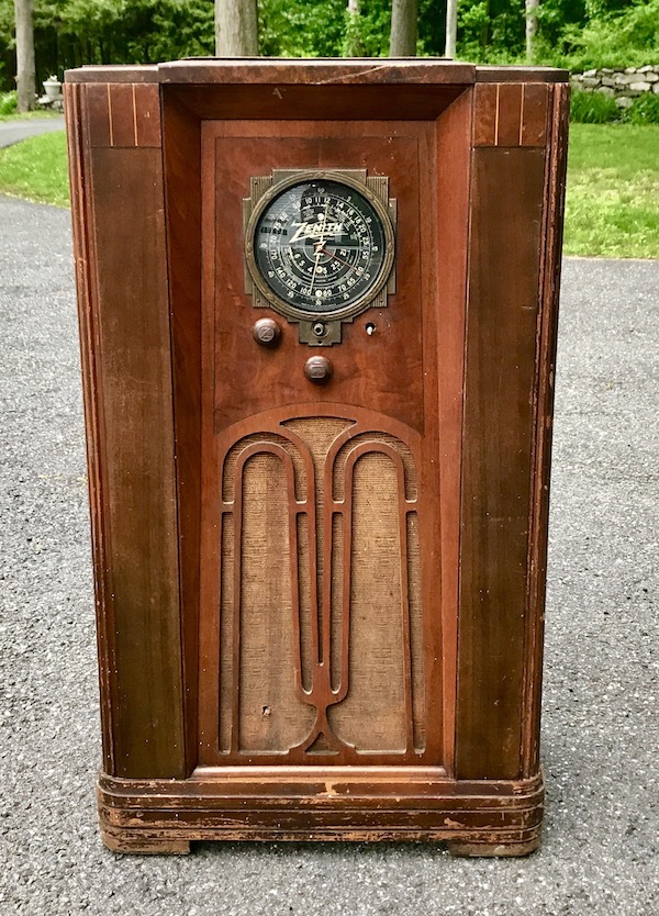
Just picked up this Zenith, model 9S54. I loved the angular art deco cabinet (which needs to be refinished- I learnt a lot from redoing my Philco 38-8, so, that will help me there!). The previous owner had been a repair technician and had passed away. It looks like he attempted to work on it, was about to, or gave up, as the chassis was loose in the cabinet and 2 knobs were missing.

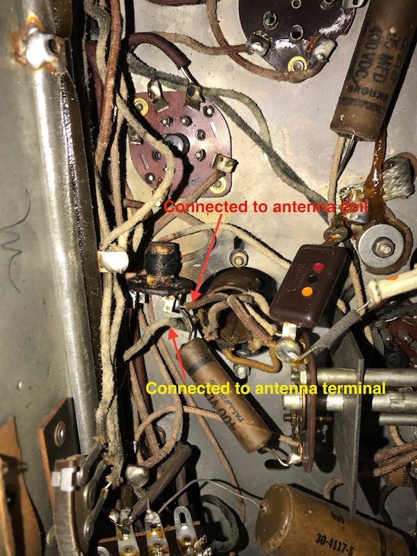
I think the radio was hit by lightning via the antenna. It appears that what I think is the antenna choke is burnt, also the antenna terminal plastic is half missing and the terminal itself is hanging out the back, but connected to the antenna coil still. The choke (or whatever this thing is), seems to have 4 terminals, one of which is connected to the antenna coil and a capacitor.

I haven't measured anything yet, but what do I replace this with? The antenna coil itself has no burn marks, and I don't see any elsewhere in the radio... but what else could have been affected?
The cabinet is pretty nice, just one big scratch in front but otherwise I know will look great refinished. The speaker is in good shape too. The rest of the radio looks fairly normal. Most capacitors are original, one is a replacement marked Philco. A tube has the date 1938 on it from a radio shop in NYC, and someone wrote on the chassis a date of 1945 (probably when that capacitor was replaced).
Posts: 1,475
Threads: 69
Joined: Nov 2012
City: Kansas city, MO.
Hi Adam. I'm adding a schematic link to your chassis to help anyone looking to answer your questions.
http://www.nostalgiaair.org/Resources/465/M0025465.htm
Posts: 4,808
Threads: 54
Joined: Sep 2008
City: Sandwick, BC, CA
What you will need to do is confirm that the antenna coil is actually burned out on the primary side with an Ohm meter, as well as that choke. It may be helpful to find out what is supposed to be there and what is not, if that small coil/choke is supposed to be there then it was probably a wave trap of some sort, and if it is burned out you can just bypass it if the antenna coil itself is still good. In some sets they would wind the antenna coil windings for each band on the same form which can make replacement difficult, though rewinding a broadcast band primary is a possibility unless you can find a replacement from a parts chassis.
Regards
Arran
Posts: 21
Threads: 7
Joined: Apr 2017
City: Weston, CT
Thanks Arran, I found a photo of the same chassis and it does have the small choke there. I think it's on the schematic as an antenna choke, with one side going to ground. I didn't even think of the antenna coil being burnt out... And it does look like it has all bands on one coil. I will check it, but I wonder if this is the reason the set never got repaired 60+ years ago.
Posts: 16,241
Threads: 564
Joined: Oct 2011
City: Jackson
State, Province, Country: NJ
If this is the choke 10, it is not a band coil, the #1 is.
Isn't it some form of the IF trap? It seems like it could be shorted if it is the trap, or, if desired, replaced with any 1mH choke.
People who do not drink, do not smoke, do not eat red meat will one day feel really stupid lying there and dying from nothing.
Posts: 4,808
Threads: 54
Joined: Sep 2008
City: Sandwick, BC, CA
Mike is right, the parts list says that the choke is 1 millihenry (not 10 mh), which means that you can still find a replacement if you need to, but I would check that antenna coil primary too. I think the choke was intended as a wave trap, if it is burned out hopefully it acted as a fuse and saved the antenna coil primary from burning up as well since it connected closed to ground.
Regards
Arran
Users browsing this thread: 2 Guest(s)
|
|
Recent Posts
|
|
New member
|
| Hello jeff,
Welcome aboard !
Sincerely Riochardradiorich — 06:53 PM |
|
New member
|
| Good picture,
When was it taken? You don't look in it like a guy who has a teenage son :)morzh — 06:13 PM |
|
New member
|
| Love the pic! I'm southern IL, so wouldn't be much help and Bob Anderson is very good on those, but lives in Chicago are...TV MAN — 05:25 PM |
|
Philco 40-120C Filament Wiring
|
| :thumbup:klondike98 — 04:56 PM |
|
Philco 40-120C Filament Wiring
|
| With these values I think you are OK; the Cmax for this tube is 40uF.
Your Vbb could rise a bit, but probably not too mu...morzh — 04:53 PM |
|
Philco 40-120C Filament Wiring
|
| BTW, someone had replaced the original 20uF/20uF filter cap with a 47uF/33uF cap. Do you think these values are safe on ...bluecap — 04:33 PM |
|
Philco 40-120C Filament Wiring
|
| You're correct. I was misinterpreting the key position. I now know where it is, and things are making sense. I appreciat...bluecap — 04:29 PM |
|
Philco 40-120C Filament Wiring
|
| I think Morzh has a good thought. Check the key position. The under chassis diagram in the Philco info shows an “H” for ...klondike98 — 04:25 PM |
|
Philco 630csx power cord
|
| Yes, the third wire goes to the stud on the side and is separate from the other two.
I've usually used cloth covered ...Tynwald — 03:09 PM |
|
New member
|
| Have you tried Alabama Historical Radio Society?
They possibly could recommend someone.
I remember a name of Dee Hanes...morzh — 03:08 PM |
|
Who's Online
|
There are currently 4788 online users. [Complete List]
» 2 Member(s) | 4786 Guest(s)
|
|
|

|
 
|


![[-] [-]](https://philcoradio.com/phorum/images/bootbb/collapse.png)


