01-02-2024, 12:13 AM
I recently purchased a Philco 80 Jr. at an electronics club meet. It's case was in good shape and the inside looked fairly clean. When I got it home, I checked the transformer to make sure there were no opens. It tested good so I repacked the Bakelite capacitors, replaced the filter electrolytics, and replaced the resistors/capacitors that were out of spec. I was feeling pretty good about the restore and put it on my isolation transformer, variac, and dim bulb tester. It came up with no shorts and the dial light illuminated. But, nothing came out of the radio. If I touched the Type 42 Output tube, I could hear hum from the speaker. After further testing I discovered the oscillator was not oscillating. Further testing revealed the tickler coil was open.
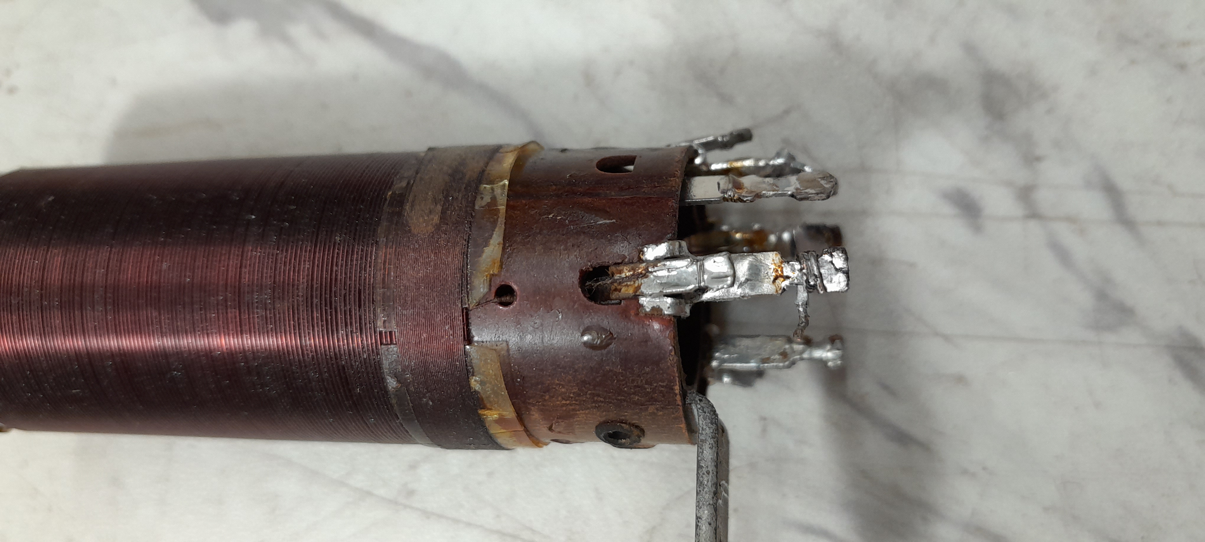
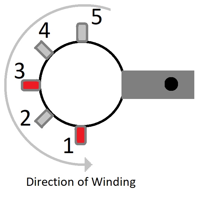
I removed the oscillator from the radio and tested the coil at the wire connections. Still no continuity. I photographed the coil from multiple angles. Then, I started unwrapping the coil starting from pin 1. I made sure to document the direction of the winding as I removed it. After about three winds, I found the open. I continued to unwind the coil. I counted 35 turns unwinding and 35 turns looking at the photograph. I used my cell phone to take the picture, and then zoomed in to count. It actually worked very well.
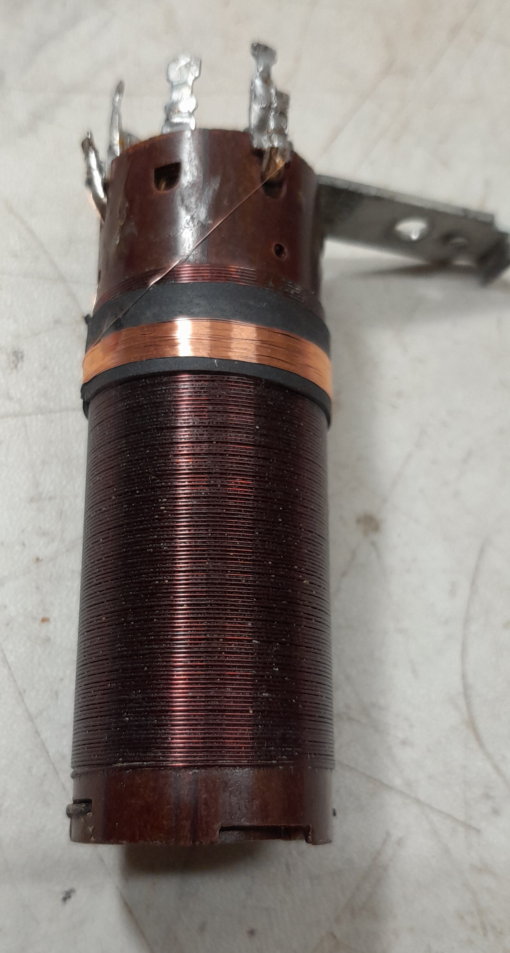
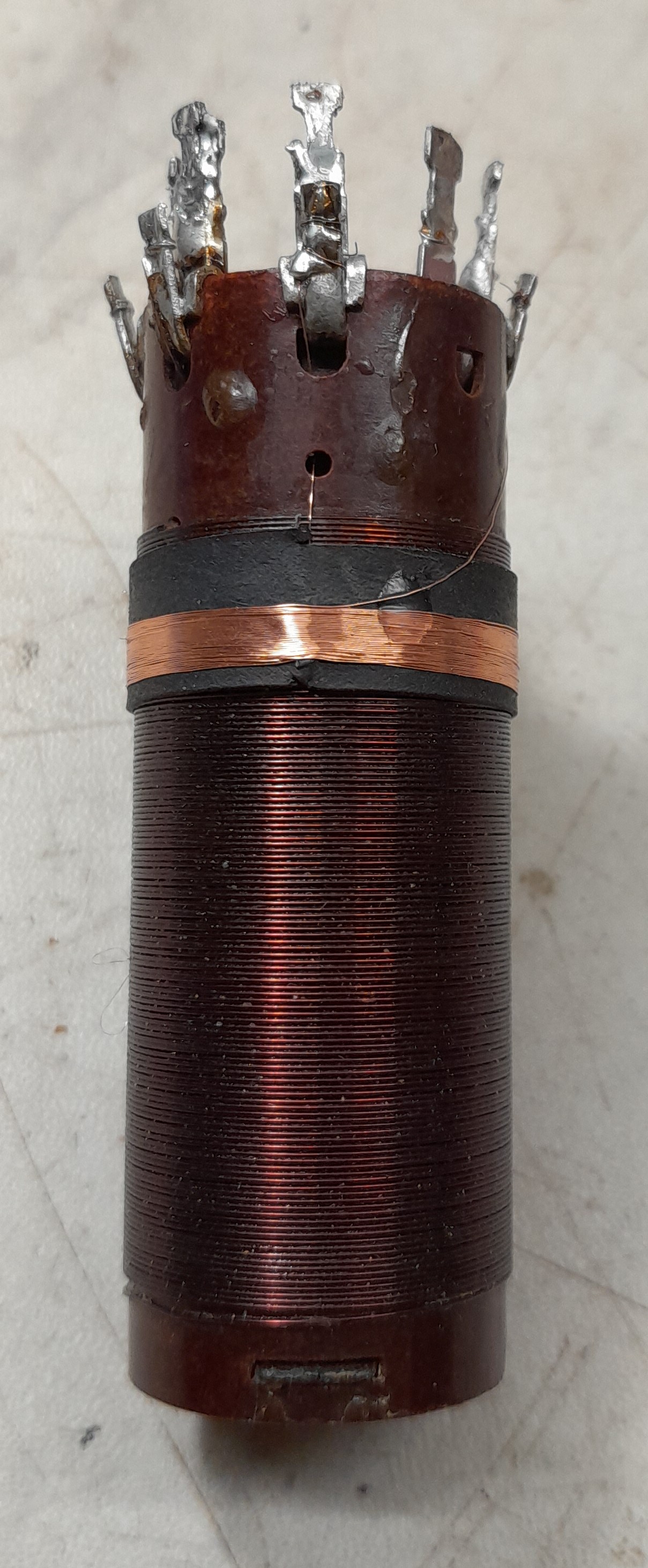
I removed the old celluloid to stop it from corroding the new wire I was about to wind. I was racking my brain as to what to use to separate the big coil from the tickler. I decided on using some shrink wrap tubing. It fit almost perfectly. I ran the new wire from the roll (38 ga), through the shrink wrap, and through the holes on the oscillator to connector three. I slid the shrink wrap into place and heated it slightly to snug it up. I cut a small notch in the shrink wrap to provide a stable point to start wrapping the wire.
I made a makeshift holder for the spool of wire so I could unroll it smoothly. I slowly and carefully wound the new coil on top of the shrink wrap, making it as neat as possible without breaking the wire. After 35 turns, I placed a small drop of white glue to secure the end. I let the glue dry before threading the wire through the holes for Pin 1. Stripped the end of the wires, soldered them to their posts, checked for continuity, and returned the oscillator to the radio.
I slowly brought the radio back up and checked the oscillator. It was working, but nothing was coming out of the speaker. After rechecking my previous work, I found a wire that I had neglected to reconnect. It was the Screen Grid wire for the "Output" tube. After reconnecting the wire, I brought up the radio and it was working again!
My takeaway from this experience is "don't let the oscillator intimidate you." It's an easy fix for the tickler coil as long as you document as you go along. I hope this helps someone with their radio repair. I have attached a before and after picture of the repair, plus a diagram showing direction of winding for my oscillator (your mileage may vary).


![[-] [-]](https://philcoradio.com/phorum/images/bootbb/collapse.png)


