Posts: 13
Threads: 2
Joined: Feb 2014
City: Maine
Forum members,
I have a Philco model 38 Farm radio in restoration. I need to build a power supply for it to replace the batteries. I remember seeing some time ago a schematic that showed the circuit. I believe the circuit had connected several zeners to arrive at the various voltages needed. It was simple and clever. I started looking for the diodes, but lost the paper and with it the design. Has anybody in this forum built this before? I thought perhaps Ron Ramirez might remember. I think that it tapped +135vdc, +67.5vdc, +2vdc, -3vdc, and -7vdc. These are the listed source voltages for the 38, per the schematic. Otherwise, I'll need to breadboard something up and experiment.
St Tee
Posts: 16,226
Threads: 563
Joined: Oct 2011
City: Jackson
State, Province, Country: NJ
If using zeners I would use zeners with a wide range Iz. They should withstand the power equal Iz-max times Uz at about 14-15mA.
Then I would put two in them that are 68V in series, and in addition serialize a 3V and 7V zeners. Reference the point where the two connect to the lower 68V zener as a GND.
You will need a separate power source for 2V filaments. Could try AC, but filtered DC is cleaner.
Why 15mA?
Your B+ battery drain is 8-12mA and you need the zeners to withstand this current without load. The zeners should preferably still stabilize at about 2-3mA of current, which will be the case when the load is connected.
However Zeners are bad regulators to power up things - they are mostly used as references, so if you could make a clean DC power source, that would be better.
Again you need all voltages at low current except 2V (700mA).
Posts: 1,231
Threads: 29
Joined: Jan 2014
City: Wellborn Florida


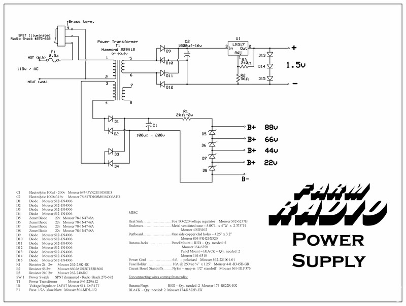
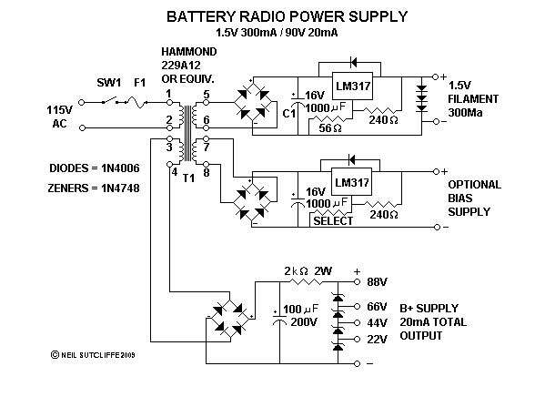
Hope this download thing works
Posts: 1,231
Threads: 29
Joined: Jan 2014
City: Wellborn Florida

Sorry about last post ! David
Posts: 4,806
Threads: 54
Joined: Sep 2008
City: Sandwick, BC, CA
One problem though, none of those designs supplies the 135 vdc you need. You don't really need Zener diodes in a B+ supply anyhow, those battery eliminators from the 1940s and 50s used a Pi filter like an AC/DC set and there was minimal hum or ripple with the right size electrolytics. If you used a filter choke, or a solid state substitute, there would be no ripple.
I have a schematic someplace from a Radio Craft magazine that uses an old style circuit where they supply the bias voltages through a resistor network in the B- through a resistor network. I may have it on file someplace as I sent it to Bob for his Philco 623 project. These days you can hook up diodes backwards to achieve the same result off of a cheap transformer.
Regards
Arran
Posts: 1,231
Threads: 29
Joined: Jan 2014
City: Wellborn Florida
I have never used the two design I posted placed here for your use. On the farm radio I have, use a D cell for the filments and 90 volts dc for the B+. The design was found on Phil's old radios look under building, what a nice site. To get 135 volts dc connect a full bridge rect to line voltage(120) add a 47UF cap and resistors to get the correct voltage for your current draw. Line voltage divided by .707 gives peak voltage which the Ecap will charge to without a bleeder resistor. I am sure the EEs will be alone to help explain what I am trying to say. David
Posts: 13,776
Threads: 580
Joined: Sep 2005
City: Ferdinand
State, Province, Country: Indiana
It's been many years since I built any power supplies such as what St Tee described, and like the ones David posted. I would have to search for my notes...and since I moved, I still don't know where some of my stuff is... 
--
Ron Ramirez
Ferdinand IN
Posts: 13
Threads: 2
Joined: Feb 2014
City: Maine
many years ago I looked at spice to do software simulation of circuit behavior . It 's a bit of overkill for this but there is open source software available that can model a circuit to see what components would work. It just might be a fun experiment. I am 25 years removed from this work but it's good to get back into the flow. BTW, the circuit I saw some time ago belonged to Ron, so it went beyond the napkin note phase as it was online somewhere.
Posts: 16,226
Threads: 563
Joined: Oct 2011
City: Jackson
State, Province, Country: NJ
Guys,
you do not need a simulator to do this kind of jobs.
Using Spice for this is, as we say, like using a cannon to shoot sparrows.
As for free Spice, LTSpice (fom Linear Tech) is a good tool and is fully free.
Posts: 13,776
Threads: 580
Joined: Sep 2005
City: Ferdinand
State, Province, Country: Indiana
St Tee Wrote:BTW, the circuit I saw some time ago belonged to Ron, so it went beyond the napkin note phase as it was online somewhere.
Yes, you did see it - and it was right here in the Phorum!
http://philcoradio.com/phorum/showthread.php?tid=469
(I had to do a Google search to find this. B-B-B-Bing didn't bring it up.)
--
Ron Ramirez
Ferdinand IN
Posts: 13
Threads: 2
Joined: Feb 2014
City: Maine
Posts: 13
Threads: 2
Joined: Feb 2014
City: Maine
To MORZH about using Spice: You're absolutely right. Started digging back in to it and realized that it was way too much. I then started drawing up a circuit when Ron gave us his reference. Thanks to all, and save the sparrows!
Users browsing this thread: 1 Guest(s)
|
|
Recent Posts
|
|
Philco 91 Restore Code ??
|
| Well, this cap you showed cannot possibly, due to the way it is constructed, be 1000pF (0.001).
It can be in tens of pF....morzh — 03:13 PM |
|
Philco 91 Restore Code ??
|
| I have two schematics for this radio one shows the 47 block (126-226) and the other (121-221) does not. My radio does no...dconant — 02:32 PM |
|
Philco 91 Restore Code ??
|
| No, that cannot be the 47.
The 47 is a regular backelite block cap. Look at the chassis picture, it is shown there. Rig...morzh — 01:45 PM |
|
Philco 91 Restore Code ??
|
| I have changed the title of this thread from Philco 91 Schematic.
I have gone through most of the cap replacements. I...dconant — 01:26 PM |
|
462ron
|
| Here is an online transistor substitution site…
Ron462ron — 08:44 AM |
|
1930s Stewart-Warner Tombstone Radio need help identifying model number
|
|
One way to repair a broken wire on a coil is to take a copper strand out of some 18 gauge electrical cord, make a &quo...captainclock1988 — 12:55 AM |
|
B&K 1077B no video
|
| Hello Tim,
I once had a Jcpenny 13inch tv /monitor built by NEC come into my repairshop it would start acting up at tim...radiorich — 10:59 PM |
|
Restoring Philco 96
|
| Mike;
The last time I took a potted condenser can apart, and it was maybe 1/4 the size of the one in the model 96, I ...Arran — 10:56 PM |
|
Compatible crts
|
| Bob Andersen — 08:58 PM |
|
1930s Stewart-Warner Tombstone Radio need help identifying model number
|
| One way to repair a broken wire on a coil is to take a copper strand out of some 18 gauge electrical cord, make a "...Arran — 08:41 PM |
|
Who's Online
|
There are currently 2430 online users. [Complete List]
» 2 Member(s) | 2428 Guest(s)
|
|
|

|
 
|


![[-] [-]](https://philcoradio.com/phorum/images/bootbb/collapse.png)


