09-12-2014, 05:37 PM
Hello everyone
This is my first post to the Philco Phorum and I would like to inform everyone that I'm just a novice weekend radio restorer. Please keep that in mind when I ask beginner questions. I'm just starting my third radio restoration and I've got some questions about
 the electrolytic cans for my Philco 116B (early model) radio. Correct me if I'm wrong but these are the three cans:
p/n 30-2121 1.0uf-3.0uf-2.0uf-1.0uf
p/n 30-2025 8.0uf
p/n 30-2045 8.0uf-10.0uf
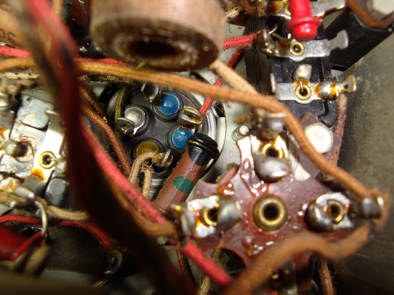
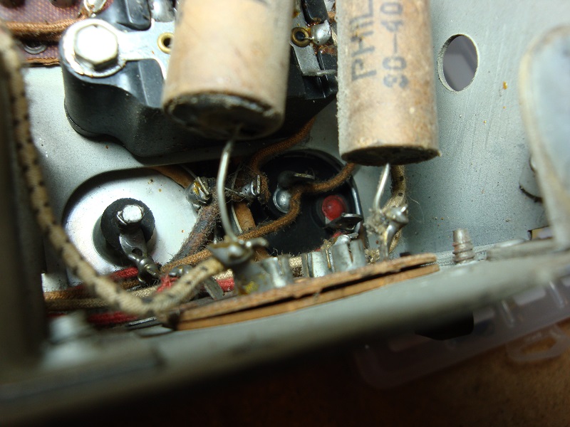
I'm attaching a couple of pics showing some sort of "color coding" on the bottom of these cans and I would like to know what they represent. Such as the bottom of the 4 cap 30-2121 shows "silver,blue,blue, yellow. Do they represent the 4 values of the caps? Is there a web site out there that explains the different types of these canisters?
Also, is it better, when replacing them, to stick with the closest possible values or to go to a higher value? I can never get a straight to that.
Thanks to all responses
Jeff
This is my first post to the Philco Phorum and I would like to inform everyone that I'm just a novice weekend radio restorer. Please keep that in mind when I ask beginner questions. I'm just starting my third radio restoration and I've got some questions about
p/n 30-2121 1.0uf-3.0uf-2.0uf-1.0uf
p/n 30-2025 8.0uf
p/n 30-2045 8.0uf-10.0uf
I'm attaching a couple of pics showing some sort of "color coding" on the bottom of these cans and I would like to know what they represent. Such as the bottom of the 4 cap 30-2121 shows "silver,blue,blue, yellow. Do they represent the 4 values of the caps? Is there a web site out there that explains the different types of these canisters?
Also, is it better, when replacing them, to stick with the closest possible values or to go to a higher value? I can never get a straight to that.
Thanks to all responses
Jeff


![[-] [-]](https://philcoradio.com/phorum/images/bootbb/collapse.png)


