Welcome Guest! Be sure you know and follow the Phorum Rules before posting. Thank you and Enjoy! (January 12) x

Thread Closed
Thread Rating:
  • 0 Vote(s) - 0 Average
  • 1
  • 2
  • 3
  • 4
  • 5

GE A-70 vernier operation
#1

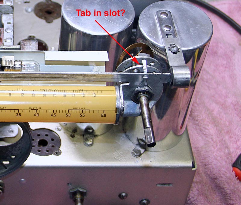
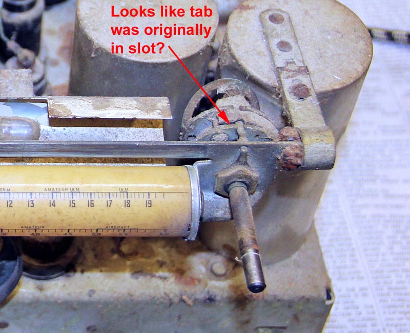
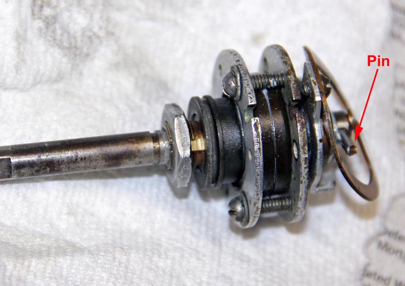
I am having trouble understanding the operation of the vernier control on my GE A-70. I took it apart and cleaned, lubricated it and re-installed it with along with re-stringing the rotating dial. Everything works great except the pointer does not move during fine adjustment. There is only one shaft which I think should automatically switch from fine to coarse when the pin hits the stop on the rear of the control (I attached photos showing the pin and tab).

If I place the tab on nut into the slot on the front of the vernier it prevents the control from switching to coarse and limits the dial travel.  However it appears from my photo of the original set up that the tab is in the slot so I am confused. can anyone shed some light on how this control is supposed to be set up.

Thanks,

Steve D
           
#2

The tab does look like it belongs in the slot. I see a snap ring in the original photo. Was that just holding what appears to be a dust cover or is something possibly missing?
#3

Thanks for you response. I don't see a snap ring and don't remember one when I took it apart.  What appears to be a dust cover I think was actually some dust itself.  The whole vernier was clogged up with dust.

Steve D
#4

I solved this issue by adjusting the three clamping screws to get the proper preload on the ball bearings. I had the screws tightened down too much. The tab does indeed need to be in the slot to prevent rotation of the vernier body and then the screws adjusted for proper operation. This vernier control is intuitive and works very well when adjusted properly.

Steve D


Users browsing this thread: 3 Guest(s)
[-]
Recent Posts
Philco 46-480 Electronic Restoration
Late last night a guy reached out in response to my posting on the Antique Radio Forum and suggested I contact Trust Aut...jrblasde — 11:01 AM
Philco 630csx power cord
Have you opened up that plug? It may be that the third wire is connected to that brass stud on the side of the plug and ...Arran — 02:57 AM
Model 27-84 BUZZ?Humm?
I would have to look at the schematic but it's not uncommon in 1930s AC radios to have the negative of one filter cap co...Arran — 02:46 AM
Model 27-84 BUZZ?Humm?
Hello Bruce, First all do mean a 37-84b ? Did you take any before and after pictures ? is it a buzz like when you touch...radiorich — 01:59 AM
B&K 1077B no video - problem solved
Hello Tim, Yes, I even check all of my replacement parts when I install them and I too had a capacitor go bad not long a...radiorich — 01:54 AM
B&K 1077B no video
I got back into it tonight. Problem found and resolved! Sometimes it helps to take a break and think things over. It was...TV MAN — 12:40 AM
6TPZ and 5TPO Radio Help
Thank you. I have to take a break from it for about a week. I'll have to do some thinking. I was toying with the idea ...R3Sons — 12:21 AM
Model 27-84 BUZZ?Humm?
Drowning in a overloud buzz/Humm. Have already changed filter caps,bakelite blocks( caps),out of speck resistors,checked...Bruce — 12:17 AM
Philco 630csx power cord
Hello Mike Here is the Link to the company the place is called Grand Brass lamp parts . I buy all my Lamp parts plus ...radiorich — 12:00 AM
Philco 40-120C Filament Wiring
Is the tube in your radio actually 35Z3 or 35Y4, or something else?morzh — 10:55 PM

[-]
Who's Online
There are currently 2789 online users. [Complete List]
» 2 Member(s) | 2787 Guest(s)
AvatarAvatar

>